
Column

29 articles


Article Summary

OKI Electric Cable's "ORP-30F" is an AWM-approved, ultra-slim, high-flex robot cable rated for 30V, specialized for internal wiring. It achieves up to a 32% outer diameter reduction compared to conventional products, making it highly suitable for narrow routing in moving parts. This article explains the technical specifications and benefits of this series, which leverages a unique special elastomer and a heat- and oil-resistant reinforced PVC sheath to deliver outstanding durability.

Introduction

As industrial robots and machine tools become more multifunctional and compact, the wiring space within these systems has become extremely narrow. Balancing space-saving designs with wire breakage prevention in moving parts is a major challenge for mechanical, electrical, and production engineers alike. This column highlights OKI Electric Cable's "ORP-30F Cable Series". Operating under UL758 Style 21103 (rated at 105°C and 30V), this series achieves up to a 32% outer diameter reduction compared to conventional cables while providing the high durability required to withstand harsh motions such as sliding, swiveling, and twisting. Below, we detail its structural design, electrical characteristics, and mechanical motion specifications.


【Product Overview and Key Features】Concept of an Ultra-Slim Design Specialized for Internal Wiring

The "ORP-30F Cable Series" by OKI Electric Cable is a high-flex robot cable series rated for 30V and optimized for internal system wiring. Wiring paths around moving elements are often complex and tightly confined.

The most striking feature of this product is its outer diameter reduction of up to 32% compared to conventional robot cables. By minimizing the overall outer diameter, engineers can route these cables through tight spaces where cable interference or minimum bending radius limitations previously prevented effective layouts. Its lightweight design also reduces loads on moving components, facilitating smoother machine motion.


【Structure and Materials】Proprietary Design Delivering Superior Mechanical and Dynamic Durability

The exceptional performance of the "ORP-30F" is driven by carefully selected materials and a refined internal design.

  • Conductors (Core Wire): Conductors utilize tin-plated annealed copper wire (or stranded wire) for superior flexibility and corrosion resistance. This minimizes metal fatigue from repeated bending, ensuring long-term electrical reliability.
  • Insulation: Features a proprietary "special elastomer" known for its exceptional flexibility and mechanical strength. This material reduces internal friction and disperses bending stress during dynamic movement, providing superior flex life.
  • Shielding: Shielded versions utilize a tin-plated annealed copper wire braid to shield against external noise. This effectively reduces electromagnetic interference (EMI), stabilizing low-voltage or micro-signal transmissions from encoders and sensors.
  • Sheathing (Outer Jacket): The outermost jacket is made of heat-resistant and oil-resistant reinforced PVC (Polyvinyl Chloride), allowing it to withstand harsh environments exposed to industrial oils or cutting fluids. The sheath features a matte black finish, which minimizes light reflection and keeps a clean aesthetic.
  • Flame Retardancy: Meets horizontal flame test standards, ensuring safety when integrated inside electrical equipment.

【Dynamic Durability Performance】Durability Proven in Three Motion Modes: Sliding, Swiveling, and Torsion

The "ORP-30F Cable Series" offers exceptional durability under mechanical stress. Under OKI Electric Cable's proprietary test methods, it has achieved outstanding reference performance values across three primary motion modes (Note: these values are for reference only and are not guaranteed):

  • Sliding Bending Life (50 million cycles or more): Bending radius set to approx. 10x cable outer diameter (OD), sliding speed of 70 cycles/min, and travel distance of 350 mm (one round-trip counts as one cycle). Excellent for drag chain installations.
  • Swiveling Bending Life (10 million cycles or more): Bending angle of ±90°, speed of 40 cycles/min, load of at least 2.94 N (one round-trip counts as one cycle). Bending radius is approx. 15x cable OD for 34–30 AWG, and approx. 8x cable OD for 28–22 AWG. Highly suited for robot articulation joints.
  • Torsion/Twisting Life (10 million cycles or more): Twisting angle of ±180°, speed of 70 cycles/min, and span distance of 500 mm (one round-trip counts as one cycle). Ready for twisting motions in robot arm axes.

【Detailed Technical Specifications】Selection of Layer-Stranded / Twisted-Pair Types and Electrical Characteristic Data

This series offers an extensive lineup of 224 distinct part numbers, spanning wire sizes from 34 AWG to 22 AWG to accommodate various signal and power requirements.

Size-Specific Specifications:

Across all sizes, the insulation resistance (at 20°C) is 100 MΩ・km or higher, and the dielectric strength is AC 500 V for 1 minute.

AWG SizeConductor Cross-Section (mm²)Conductor Composition (wires/mm)Insulation Outer Diameter (mm)Conductor Resistance (20°C Ω/km)
340.0212/0.050.4860 or less
320.0419/0.050.45550 or less
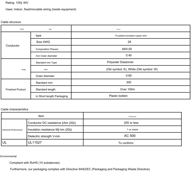
300.0530/0.050.52340 or less
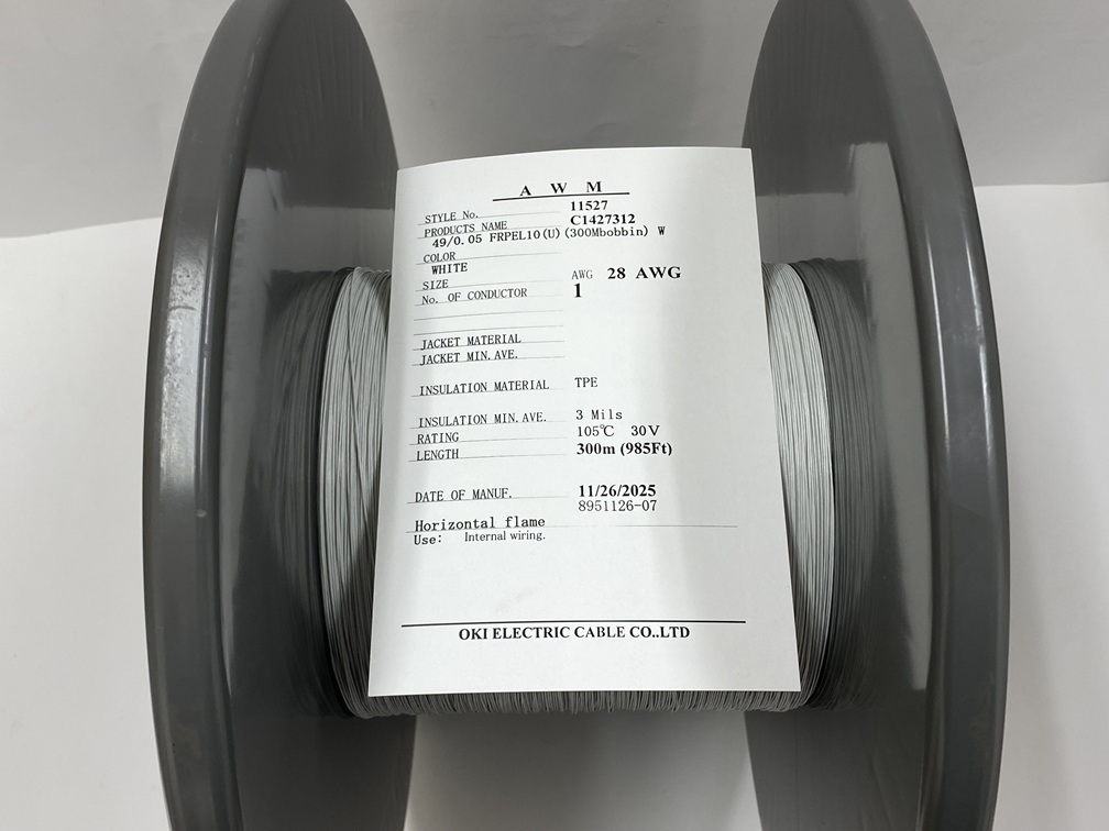
280.149/0.050.6205 or less
260.1578/0.050.77130 or less
240.2587/0.060.9180 or less
220.35125/0.061.0361 or less

(Note: Insulation outer diameters and conductor resistances represent nominal and maximum values, respectively.)

Lineup Classifications:

  • Layer-stranded type: Available in 2 to 10 cores across all AWG sizes.
  • Twisted-pair type: Available in 2 to 10 pairs for unshielded, and 2 to 10 pairs for shielded versions. Notably, a 20-pair configuration is exclusively available for the 24 AWG shielded model.

Allowable Current Examples (calculated reference values at an ambient temperature of 30°C, single cable installed in open air):

  • Layer-stranded type (unshielded):
    • 34 AWG: 2 cores = 1.0 A, 10 cores = 0.5 A
    • 22 AWG: 2 cores = 6.5 A, 10 cores = 3.6 A
  • Twisted-pair type (shielded):
    • 34 AWG: 2 pairs = 0.8 A, 10 pairs = 0.4 A
    • 22 AWG: 2 pairs = 5.0 A, 10 pairs = 2.8 A

【Key Installation Design Considerations】Allowable Bending Radius and Core Identification Methods

To maximize the service life of the "ORP-30F", it is critical to observe the recommended minimum bending radius limits during installation design:

  • Fixed wiring: 4x cable OD or larger
  • Dynamic wiring (unshielded): 6x cable OD or larger
  • Dynamic wiring (shielded): 8x cable OD or larger

Outer Diameter (Nominal) Examples:

For a layer-stranded 30 AWG cable, the unshielded version has a nominal OD of 2.3 mm (2 cores) or 3.2 mm (10 cores), while the shielded version has a nominal OD of 2.6 mm (2 cores) or 3.5 mm (10 cores). Ensure sufficient clearance and appropriate bending paths based on these outer diameters when designing dynamic cable routing.

Core Identification:

To prevent wiring errors, the series utilizes clear color identification:

  • Layer-stranded (Cores 1–10): 1: Black, 2: White, 3: Red, 4: Green, 5: Yellow, 6: Brown, 7: Blue, 8: Gray, 9: Orange, 10: Purple.
  • Twisted-pair (Pairs 1–10): Pair 1: Blue + White, Pair 2: Yellow + Brown, Pair 3: Green + Black, Pair 4: Red + Gray, Pair 5: Purple + Orange, Pair 6: Blue + Brown, Pair 7: Yellow + Black, Pair 8: Green + Gray, Pair 9: Red + Orange, Pair 10: Purple + White (each pair consists of Core 1 and Core 2).

【Applications and Target Fields】Specific Scenarios from Robotics to Machine Tools

Due to its extremely slim profile and robust mechanical properties, the "ORP-30F Cable Series" is widely adopted in industrial automation and FA systems:

  • Internal Wiring for Sensors, Switches, and Encoders: Ideal for small sensor heads requiring ultra-slim lead wires, limit switches operating under low voltages (30V or less), and rotary encoders.
  • Industrial Robots and Machine Tools: Suitable for tight joints, robot arm articulations, pick-and-place systems, and rotatable sections of lathes and machining centers.
  • Drag Chain/Cable Carrier Wiring: When routing multiple cables through a constrained drag chain cross-section, this series frees up space by up to 32%, reducing mechanical friction and wear between adjacent cables.

【Manufacturer Advantages】UL Compliance and Quick Delivery for Easy Procurement

OKI Electric Cable Co., Ltd. is a well-established Japanese manufacturer of high-quality robot cabling solutions.

  • Global Compliance: Certified under UL758 Style 21103 (rated at 105°C, 30V, AWM 21103), making it highly reliable for machinery and equipment destined for international export.
  • Quick Delivery System and Small Lot Support: Highly demanded products are prepared as stock sales items (marked with ◯, inventory fluctuates constantly), establishing a system for short-delivery-time shipments. Furthermore, because it supports cut-to-length sales in 10-meter units, procurement is possible starting from small quantities.

【Summary of Technical Advantages and Applications】Consolidating Product Value

OKI Electric Cable's "ORP-30F Cable Series" is a highly practical, ultra-slim high-flex robot cable optimized for 30V applications, achieving up to a 32% reduction in outer diameter compared to conventional alternatives. Featuring premium components—such as special elastomer insulation and a matte black heat- and oil-resistant PVC jacket—it boasts outstanding dynamic performance, withstanding over 50 million sliding bending cycles, 10 million swiveling cycles, and 10 million torsion cycles. From static internal routings to dynamic joints, cable carriers, and sensor/encoder connections, the ORP-30F is the ideal choice for high-durability wiring design in narrow spaces.


◇Oki Electric Cable Web Site

https://www.okidensen.co.jp/en/prod/cable/robot/orp30f.html


◇Product sales page
ORP-30F Twisted-pair type With shielding(SB)
https://nisho-en.ocnk.net/product-list/74

ORP-30F Multi Core type Without shielding
https://nisho-en.ocnk.net/product-list/75

ORP-30F Multi Core type With shielding(SB)
https://nisho-en.ocnk.net/product-list/76


ORP-30F 28AWG×6C(SB)(21103)


Article Overview

This article explains the technical specifications and applications of the 23.8-inch 4K UHD display "LCD269-238" announced by Lincoln Technology Solutions. Featuring a 3840×2160 resolution, high brightness up to 1500 nits, a wide color gamut covering over 100% of DCI-P3, and a 4-lane eDP interface, it is well-suited for applications such as medical imaging, broadcasting, and industrial control rooms.

Introduction

In industrial fields where high-precision image display and accurate color reproduction are required, the selection of display devices is a critical factor determining system performance. Lincoln Technology Solutions (LTS), a display manufacturer based in Cary, North Carolina, USA, has announced the "LCD269-238," a 23.8-inch 4K UHD display engineered for high color reproduction and visibility. Aimed at design engineers, developers, procurement managers, and production technology specialists in the manufacturing industry, this article provides an objective explanation based on published materials regarding the optical characteristics, backlight structure, interface specifications, operating environment, and specific deployment applications in medical, broadcast, and industrial control fields.


Product Overview and Main Specifications

The "LCD269-238" (also known as the LCD269 Series) is a 23.8-inch 4K UHD (3840×2160 resolution) high-bright liquid crystal display designed for specialized applications where image quality, color reproducibility, and reliability are essential. It utilizes a high-brightness backlight structure capable of maintaining readability even in high-ambient-light environments, alongside a wide color gamut film suited for color-critical settings.

Below is a summary of the key technical specifications for the "LCD269-238" as documented in published materials.

ItemTechnical Specification / ParameterDetails / Source Extract
Manufacturer NameLincoln Technology Solutions (LTS)Based in Cary, North Carolina, USA
Product Name / Model No.LCD269-238 (LCD269)DigiKey Part Number: lcd269-238ntloncntbr0-1
Screen Size23.8 inches (23.8”) 
Resolution3840 × 2160 (4K UHD) 
Luminance (Brightness)Up to 1,500 nits (Includes 2,000-nit reference in documentation) 
Contrast Ratio1200:1 
Color Gamut CoverageOver 100% DCI-P3 (>100% DCI-P3) 
Display Color Performance8-bit (8-bit vivid color performance) 
Backlight StructureBlue LED with wide gamut film 
InterfaceeDP (4-lane, up to 5.4Gbps link rates) 
Operating Temperature Range0°C to +50°C 
Touch PanelOptional touch available upon request 

Optical Performance and Backlight Structure Features

In specialized equipment requiring high-definition image display and accurate color identification, a balanced combination of overall optical performance—beyond resolution alone—is essential.

1. 3840×2160 (4K UHD) High-Resolution Display

Achieving high pixel density on a 23.8-inch screen size with 3840×2160 pixels, it clearly reproduces detailed graphic data, medical images, and fine text displays.

2. Over 100% DCI-P3 Wide Color Gamut and 8-Bit Color

It covers over 100% of the DCI-P3 color gamut (>100% DCI-P3) widely used in digital cinema and video production. The backlight utilizes a "Blue LED with wide gamut film," enabling vivid and accurate color representation through 8-bit processing.

3. High Brightness Performance up to 1500 nits (2000 nits in some references)

It features a high brightness of up to 1,500 nits (referenced as 2,000 nits in product description copy), significantly higher than standard indoor displays. This maintains screen readability and legibility at a high level even in medical environments with strong lighting, industrial control rooms, high-ambient-light settings, or outdoor setups.

4. Power Efficiency and Screen Uniformity

The backlight system and optical film configuration achieve both uniform illumination of light and efficient power usage.


Embedded Interface and Operating Environment Specifications

When integrating into industrial equipment or embedded systems, transmission bandwidth and environmental resistance are key engineering design points.

1. 4-Lane eDP (Embedded DisplayPort) Connection

The eDP interface is adopted as the transmission standard for high-resolution 4K signals. Configuring 4 signal lanes and supporting link rates up to 5.4Gbps per lane (5.4Gbps Link Rates), the design enables stable transmission of large-volume 4K video data.

2. Operating Temperature Range (0°C to +50°C)

The operating temperature range for this display module is 0°C to +50°C. It meets standard operating environment conditions for indoor control panels, medical equipment carts, and broadcast monitoring racks.

3. Optional Touch Panel Support

Depending on user requirements and enclosure design specifications for control interfaces, touch panel functionality (Optional touch) can be added upon request.


Applications and Specific Uses

The LCD269-238 was developed for technical workspaces where image clarity, color accuracy, and stable visibility are directly required.

1. Medical Field (Medical Imaging & Surgical Visualization)

  • Applications: Diagnostic image review, surgical and procedural displays.
  • Technical Rationale: Crucial for clearly distinguishing subtle details and color variations in diagnostic images and surgical video; highly valued for its 4K resolution, accurate color rendering, and high brightness.

2. Broadcast & Video Production (Broadcast & Post-Production)

  • Applications: Broadcast studio monitoring displays, video editing and post-production environments.
  • Technical Rationale: Video production workflows require editors to have true color confidence; the wide color gamut exceeding 100% DCI-P3 is effectively utilized.

3. Industrial Control Rooms & Technical Workspaces

  • Applications: Factory/plant supervisory HMI, control room monitors.
  • Technical Rationale: In environments where rapid decision-making is essential, it prevents glare and washout even in brightly lit rooms, delivering reliable high-bright visibility.

Features of the Manufacturer (Lincoln Technology Solutions)

Lincoln Technology Solutions (LTS) is a custom display solution provider headquartered in Cary, North Carolina, USA.

  • Product Portfolio: Engaged in the development and manufacture of custom LCDs, OLEDs, and Mini-LED displays featuring Full Array Local Dimming (FALD) technology.
  • Development Structure: Houses agile internal R&D and engineering teams, providing custom design services and long-term supply support for OEM manufacturers and system integrators.
  • Sample Availability: Samples and additional technical data for the LCD269-238 are available through DigiKey (Part Number: lcd269-238ntloncntbr0-1) or via manufacturer sales contact (sales@lincolntechsolutions.com).

Summary

The 23.8-inch 4K UHD display "LCD269-238" announced by Lincoln Technology Solutions is a display module featuring a 3840×2160 resolution, maximum brightness up to 1500 nits, and a wide color gamut exceeding 100% DCI-P3. Equipped with a blue LED backlight with wide gamut film and a 4-lane eDP interface supporting up to 5.4Gbps, its operating temperature range spans from 0°C to +50°C. It serves as a practical choice in display device selection for embedded and industrial systems requiring high resolution and precise color fidelity, including medical diagnostic imaging, surgical displays, broadcast video monitoring, and industrial control rooms.


◇Manufacturer's Website

https://lincolntechsolutions.com/lincoln-technology-solutions-launches-lcd269-238-a-23-8-4k-high-bright-display-for-color-critical-applications/ 

https://lincolntechsolutions.com/products/available-products/


OKI Electric Cable’s "Long FPC" is a flexible printed circuit achieving lengths of up to 100 meters. Featuring an ultra-thin profile of approximately 0.1 mm and a weight only 1/100th of conventional round cables, it optimizes wiring efficiency in space systems, large FA equipment, and large-scale lighting. This technical column objectively details its structure, comparison with standard cabling, moisture absorption precautions, and a unique production system that supports custom orders from a single piece.


In the design of electronic devices and industrial machinery, reducing wiring size and weight, saving space, and enhancing reliability are critical challenges. For large-scale Factory Automation (FA) equipment, large lighting installations, and space development hardware, conventional round cables often create bottlenecks due to their weight, bulkiness, and the risk of miswiring during assembly.

This column provides a technical overview of "Long FPC" (Flexible Printed Circuits) from OKI Electric Cable (Oki Electric Cable Co., Ltd.) as an innovative solution to these cabling bottlenecks. We explore the technology behind manufacturing FPCs up to 100 meters long, compare them with traditional cabling methods, highlight the critical design consideration of moisture absorption, and present real-world applications including JAXA's space sail demonstrator. This article is compiled to assist design, development, purchasing, and production engineers with objective, practical data.


Basic Mechanism and Structure of FPCs (Flexible Printed Circuits)

A Flexible Printed Circuit (FPC) is a circuit board made by forming conductive metal electrical circuit patterns on a thin, insulating base film. Unlike standard rigid boards, FPCs possess excellent flexibility, allowing them to be folded, bent, and arranged in complex three-dimensional spaces. Electronic components can also be directly mounted on them, just like traditional rigid printed circuit boards.

An FPC is constructed from the following primary layers:

  1. Base Film (Insulating Material) A thin plastic film that provides electrical insulation and mechanical strength. OKI Electric Cable's FPCs primarily utilize polyimide, which offers outstanding heat resistance (withstanding temperatures of 120°C and above), radiation resistance, and electrical insulation. This ensures stable performance under extreme thermal cycles and harsh environments like outer space.
  2. Conductive Metal (Circuit Layer) Generally made of copper foil, high-precision circuit patterns are chemically etched onto the base film.
  3. Coverlay and Stiffeners An insulating coverlay film is laminated over the etched copper circuit to protect it from environmental exposure. Additionally, in areas requiring local mechanical strength—such as connector insertion points or component-mounting areas—stiffeners (reinforcing plates) are bonded to the backside of the FPC.

Technical Features and Specifications of OKI’s "Long FPC"

Conventional FPCs have typically been limited to a maximum length of approximately 0.5 meters (50 cm) due to the size constraints of standard manufacturing equipment. To span longer distances, engineers had to connect multiple FPCs using inter-board connectors or transition to conventional round wire cables.

OKI Electric Cable has overcome this limit by developing proprietary production technologies and process controls at its Gunma Plant, enabling "Long FPCs" to reach continuous lengths of up to 100 meters. This allows for seamless, single-piece cabling over long distances.

Key technical specifications and features include:

  • Structure (Layer Count): Available in single-sided (1-layer) and double-sided (2-layer) configurations.
  • Maximum Wiring Length: Supports continuous lengths of up to 100 meters for single-sided FPCs and up to 10 meters for double-sided FPCs.
  • Ultra-Thin Profile: The total thickness is exceptionally thin, measuring approximately 0.1 mm (or 0.1 mm to 0.2 mm depending on the layer stackup).
  • Significant Weight Reduction: When comparing cables of equivalent current/signal carrying capacity, the Long FPC reduces wiring weight to approximately 1/100th of conventional round cables.
  • High Durability and Motion Support: Shaping the FPC into a bellows-like accordion geometry allows it to handle sliding, twisting (torsional), and expansion/contraction movements. In standard linear sliding applications, high-flexibility configurations can achieve a durability of over 100 million cycles (depending on the bending radius and specific design parameters).

Technical Comparison: Long FPC vs. Round Cables vs. Standard FPCs

The table below highlights the technical differences and trade-offs of implementing OKI's Long FPC compared to standard wiring methods:

Evaluation MetricConventional Round CablesStandard Short FPCsOKI Electric Cable's "Long FPC"
Max Wiring LengthHundreds of meters (Virtually unlimited)Approx. 0.5 meters maxSingle-sided: 100 m / Double-sided: 10 m
Thickness / EnvelopeBulky (Requires large installation space)Ultra-thin (0.1 mm to 0.2 mm)Ultra-thin (Approx. 0.1 mm, high space efficiency)
WeightHeavy (100% baseline)Light (But restricted to short lengths)Extremely light (Approx. 1/100th of round cables)
Inter-board ConnectorsNone required for single runsMultiple connectors required for long runsNone required (Continuous, seamless wiring)
Miswiring RiskYes (High manual connection errors)None (Circuits are printed and fixed)None (Printed circuit prevents wiring errors)
Flex / Dynamic LifeModerate (Risk of fatigue and wire break)High (But limited by short length)Extremely high (Up to 100 million sliding cycles)

Key Benefits of Adoption

  1. Unmatched Weight and Space Savings The reduction in weight to 1/100th of round cabling and the ultra-thin 0.1 mm profile directly contribute to lighter systems. This is a game-changer for aerospace applications, such as rockets and small satellites, where weight dictates launch costs. It is also beneficial for high-speed moving parts in manufacturing machinery, reducing inertial momentum.
  2. Elimination of Assembly Miswiring Manually routing and terminating multiple round wires is labor-intensive and prone to human error. Because the Long FPC integrates all conductors into a pre-defined printed layout, assembly is simplified to plugging in connectors. This completely eliminates miswiring risks and speeds up installation times on the production line.
  3. Higher System Reliability via Fewer Junctions Chaining multiple standard FPCs to span a long distance introduces points of failure at every connector or sub-board junction. These joints are vulnerable to vibration, shock, and contact wear. By utilizing a single continuous Long FPC, all intermediate connectors are eliminated, maximizing physical and electrical system reliability.

Critical Design Consideration: "Moisture Absorption"

While FPCs offer excellent electrical and mechanical properties, engineers and production managers must account for a key material characteristic during assembly: Moisture Absorption.

Polyimide—the core material used in the base film—and the adhesives used in laminate layers naturally absorb moisture from the surrounding atmosphere. If an FPC undergoes sudden, intense heating (such as during reflow soldering, hand soldering, or thermal pressing) while holding absorbed moisture, the trapped water rapidly vaporizes and expands. This can cause severe physical defects, including:

  • Measling: Localized delamination at the resin-circuit interfaces, appearing as white spots.
  • Delamination: Separation of the layers (base film, copper foil, or coverlay).
  • Blistering (Voiding): Visible bubbling or puffing on the FPC surface.

Engineering Countermeasures

To prevent these defects, FPCs must undergo a Baking (Dehumidification Drying) process immediately prior to any high-temperature operations like reflow soldering. A typical baking procedure involves heating the FPCs in a dry oven at 100°C to 120°C for several hours. Because dried polyimide reabsorbs ambient moisture quickly, assembly must be completed within a specified time frame post-baking. Unused components should be sealed in moisture-barrier bags with desiccant (silica gel) and stored in a temperature- and humidity-controlled environment.

Target Industries and Real-World Applications

① Space Systems and Satellites (Contributing to "New Space")

A prominent historical milestone for OKI Electric Cable’s Long FPC was its deployment on JAXA’s (Japan Aerospace Exploration Agency) Small Solar Power Sail Demonstrator, "IKAROS" (launched in 2010). IKAROS utilized a massive, ultra-thin sail measuring approximately 14 meters square to propel itself through space using solar radiation pressure. OKI Electric Cable supplied a 14-meter-long continuous FPC that was mounted directly on the sail surface. It served as the crucial power and signal transmission lines connecting the thin-film solar cells and various scientific sensors. The FPC successfully withstood the extreme vacuum, harsh thermal cycles, and intense radiation of deep space, enabling the world's first successful solar sail flight.

In the rapidly growing "New Space" commercial satellite market, Long FPCs are increasingly sought after by private startups and venture firms. They provide a vital solution for reducing satellite mass, cutting component counts, streamlining manufacturing, and ultimately lowering rocket launch costs.

② Large-Scale Factory Automation (FA) and Industrial Machinery

In massive factory automation equipment, such as flat-panel display (FPD) manufacturing lines, semiconductor handling systems, and large-scale inspection stages, moving parts travel over several meters. Long FPCs provide highly durable signal and power transmission within cable carriers. Their low profile minimizes the required space inside moving tracks, and their proven durability of over 100 million sliding cycles dramatically reduces machine downtime.

③ Large-Scale Lighting and Architectural Installations

For linear LED lighting, large advertising displays, and architectural accent lighting that span long distances, the Long FPC serves as both the mounting substrate and the long-distance wiring board. Eliminating discrete connectors along the run allows for slimmer profiles and significantly higher long-term reliability.

OKI's Production Strength: Hybrid Manufacturing at the Gunma Plant

For purchasing departments and development engineers, initial tooling costs (NRE) and Minimum Order Quantities (MOQ) are major barriers to adopting custom FPCs, especially for prototype development or academic research.

At its Gunma Plant (located in Isesaki City, Gunma Prefecture, Japan), OKI Electric Cable operates two distinct, optimized production lines to support customers from initial prototyping through full-scale mass production:

  1. Sheet-fed (Piece-by-Piece / "Maiyo") Line for Prototypes and Small Lots This line processes FPC materials in individual sheets. It features low initial tooling costs and high operational flexibility, making it ideal for highly customized, low-volume designs. By leveraging the Sheet-fed line, OKI Electric Cable can manufacture custom Long FPCs of up to 100 meters with a Minimum Order Quantity of just a single piece (1 unit), accommodating spot prototype requests and early-stage R&D.
  2. Roll-to-Roll ("Roll-to-Roll") Line for High-Volume Mass Production This line continuously feeds raw materials from large rolls through etching, lamination, and processing steps. It provides excellent throughput and material efficiency, substantially reducing unit costs for high-volume production runs once designs are locked.

This hybrid capability—prototyping a single custom long board on the sheet-fed line and seamlessly transitioning to the roll-to-roll line for high-volume commercial production—makes OKI Electric Cable a versatile partner for both New Space startups and established industrial OEMs.


 Conclusion

OKI Electric Cable’s "Long FPC" represents a major leap in wiring technology, shattering the traditional 0.5-meter limit to deliver continuous flexible printed circuits up to 100 meters long.

By shrinking cabling weight to 1/100th of conventional round wires and maintaining an ultra-thin thickness of 0.1 mm, it offers a dramatic solution for system weight reduction and spatial optimization. The ability to span long distances without intermediate connector joints eliminates primary electrical failure points while streamlining assembly and preventing manual miswiring.

Backed by JAXA's rigorous IKAROS mission and supported by proper moisture baking protocols, the FPC delivers elite reliability under severe operating conditions. Through the Gunma Plant’s dual-line setup, OKI Electric Cable accommodates everything from a single custom prototype to high-volume manufacturing, offering an invaluable tool for modern design engineers in aerospace, factory automation, and beyond.


◇Manufacturer's Website

https://www.okidensen.co.jp/en/prod/fpc/flexible/tyouzyaku_fpc.html


Article Overview

Explore the technical equivalency and compatibility of JCS-compliant 7.5kV and 15kV N-EV high-voltage neon cables manufactured by Japanese industry leaders Nagaoka, Riken, and Shinagawa Densen.

Introduction

In high-voltage electrical installations, choosing the correct cable classification is critical to maintaining system safety, electrical efficiency, and long-term operating reliability. Among specialized industrial high-voltage wiring solutions, the N-EV cable—defined as a Polyethylene Insulated, Vinyl Sheathed Neon Cable—stands as the definitive industry standard in Japan and throughout global industrial lighting and power distribution systems. Designed primarily for the high-voltage side of neon tube circuits, discharge lamp circuits, and high-voltage power wiring within industrial facilities, N-EV cables must withstand significant continuous electrical stress and harsh environmental conditions.

For international electrical engineers, industrial system designers, and procurement managers, establishing robust and redundant sourcing channels can occasionally be hindered by subtle differences in product documentation, nominal versus calculated dimensions, and manufacturer-specific nomenclature. Within the high-quality Japanese wire and cable manufacturing sector, three prominent brands dominate the production of this specialty cable category: Nagaoka Electric Wire Co., Ltd. (長岡特殊電線株式会社), Riken Cable Technology Co., Ltd. (リケンケーブルテクノロジー株式会社), and Shinagawa Densen Co., Ltd. (品川電線株式会社).

This comprehensive technical analysis provides an objective, detailed evaluation of the 7.5kV and 15kV N-EV cables manufactured by these three leading brands. Grounded strictly in official engineering datasheets and certified manufacturer specifications, this article demonstrates that their products are physically, electrically, and regulatory equivalent, making them fully compatible and interchangeable in the field. By understanding the unified materials, exact dimensional specifications, rigorous dielectric testing standards, and matching regulatory certifications, engineering and purchasing departments can confidently implement cross-brand substitution strategies to secure their supply chains and optimize project execution.


Technical Concept and Structural Design of N-EV Cables

The high reliability of N-EV cables is a direct result of their standardized, robust layered construction. The acronym "N-EV" specifically designates its application and material composition under Japanese electrical standards:

  • N: Designed for Neon tube lighting and discharge circuits (ネオン管用)
  • E: Insulated with Polyethylene (ポリエチレン絶縁)
  • V: Sheathed with Polyvinyl Chloride / Vinyl (ビニルシース)

1. Conductor Material and Stranding Structure

The conductor is the primary path for high-voltage energy transmission and must balance electrical conductivity with mechanical flexibility. All three Japanese manufacturers—Nagaoka, Riken, and Shinagawa Densen—utilize tin-coated annealed copper wire (すずめっき軟銅線) as the standardized conductor material.

The choice of tin-coated annealed copper is dictated by crucial engineering requirements:

  • Oxidation Prevention: High-voltage electrical fields generate localized ozone and ionization, which accelerates the oxidation of bare copper. Tin plating creates a non-reactive physical barrier that prevents copper oxidation and maintains low contact resistance.
  • Corrosion Resistance: During the manufacturing process and throughout the cable's service life, exposure to atmospheric moisture, heat, or trace chemical components in the surrounding polymer layers could corrode bare copper. Tin-plated conductors are highly resistant to chemical corrosion.
  • Termination Reliability: Tin plating ensures excellent solderability and contact integrity when terminating high-voltage connections in industrial junction boxes or neon electrode housings, preventing joint degradation over decades of service.

The mechanical stranding structure is identical across all three brands: the conductor consists of 19 strands of 0.35 mm diameter wire (19/0.35 mm). This multi-wire stranded design achieves a uniform overall conductor outer diameter of 1.8 mm, providing the necessary flexibility for routing through tight industrial conduits and complex architectural layouts.

2. Polyethylene (PE) Dielectric Insulation

For high-voltage operations up to 7,500V or 15,000V, the choice of primary insulation is critical to prevent dielectric breakdown and minimize electrical leakage. N-EV cables use premium-grade Polyethylene (PE) as the primary dielectric barrier.

  • Polyethylene features an exceptionally high dielectric strength (typically exceeding 20 kV/mm) and a very low dielectric constant (around 2.3), combined with a minimal dissipation factor (tan δ). This ensures that electrical energy is not dissipated as heat within the cable insulation, preventing thermal runaway.
  • The polyethylene insulation is maintained in its natural color (translucent / semi-clear) across all three manufacturers. This is an intentional engineering decision: adding coloring pigments (such as carbon black or organic dyes) introduces trace carbonaceous or metallic particles. These particles can act as micro-concentrators of electrical stress under high voltages, increasing the risk of localized electrical treeing and dielectric breakdown. Keeping the PE in its natural state ensures maximum chemical purity and uniform insulating performance.

3. Polyvinyl Chloride (PVC) Outer Protective Sheath

While polyethylene provides outstanding electrical insulation, it is susceptible to mechanical tearing, abrasion, environmental weathering, and ultraviolet (UV) degradation. To safeguard the inner core, N-EV cables feature an outer protective sheath made of Polyvinyl Chloride (PVC), referred to in Japanese engineering specifications as Vinyl (ビニル).

  • The outer sheath is standardized in Grey across all three manufacturers, facilitating easy identification of high-voltage lines in cable trays and conduits.
  • This vinyl sheath provides high mechanical toughness, resistance to environmental moisture, and excellent self-extinguishing, flame-retardant properties. Under Riken's certified specifications, the vinyl sheath is engineered to pass the 60°C incline flame retardancy test (60℃傾斜難燃性試験), ensuring that any accidental combustion naturally extinguishes within 60 seconds.

Detailed Dimensional Specifications and Tolerances

Physical dimensions and tolerances are critical for ensuring that cables can be installed interchangeably. In industrial installations, cables are routed through standard conduits, cable trays, and sealing glands. Any variation in the finished outer diameter or wall thickness could cause issues with conduit fill ratios or gland sealing.

The tables below provide a direct technical comparison of the 7.5kV and 15kV N-EV models manufactured by Nagaoka Electric Wire, Riken Cable Technology, and Shinagawa Densen:

1. Technical Specification Comparison: 15kV N-EV Cables

ParameterNagaoka Electric WireRiken Cable TechnologyShinagawa DensenTechnical Equivalency Status
Product Model / Code15kV N-EV15KV N-EV (TS-010103-2)15kV N-EVCompatible
Conductor Area (Nominal)2.0 mm²1.83 mm² (Calculated)2.0 mm²Equivalent (Identical conductor)
Conductor Construction19 / 0.35 mm19 / 0.35 mm19 / 0.35 mmIdentical (19 strands, 0.35 mm dia.)
Conductor Outer Diameter1.8 mm1.8 mm1.8 mmIdentical
Insulation MaterialPolyethylene (PE)Polyethylene (PE)Polyethylene (PE)Identical
Insulation Thickness2.0 mm2.0 mm (Standard)2.0 mmIdentical
Insulation Outer Diameter5.8 mm5.8 mm (Standard)5.8 mmIdentical
Outer Sheath MaterialPVC / Vinyl (Grey)PVC / Vinyl (Grey)PVC / Vinyl (Grey)Identical
Outer Sheath Thickness0.8 mm0.8 mm (Standard)0.8 mmIdentical
Finished Outer DiameterApprox. 7.4 mmStandard 7.4 mmApprox. 7.4 mmEquivalent (Within tolerance)
Approximate Cable Weight64 kg/kmNot Specified65 kg/kmEquivalent (Difference < 1.6%)

2. Technical Specification Comparison: 7.5kV N-EV Cables

ParameterNagaoka Electric WireRiken Cable TechnologyShinagawa DensenTechnical Equivalency Status
Product Model / Code7.5kV N-EV7.5KV N-EV (TS-010102-2)7.5kV N-EVCompatible
Conductor Area (Nominal)2.0 mm²1.83 mm² (Calculated)2.0 mm²Equivalent (Identical conductor)
Conductor Construction19 / 0.35 mm19 / 0.35 mm19 / 0.35 mmIdentical (19 strands, 0.35 mm dia.)
Conductor Outer Diameter1.8 mm1.8 mm1.8 mmIdentical
Insulation MaterialPolyethylene (PE)Polyethylene (PE)Polyethylene (PE)Identical
Insulation Thickness1.0 mm1.0 mm (Standard)1.0 mmIdentical
Insulation Outer Diameter3.8 mm3.8 mm (Standard)3.8 mmIdentical
Outer Sheath MaterialPVC / Vinyl (Grey)PVC / Vinyl (Grey)PVC / Vinyl (Grey)Identical
Outer Sheath Thickness0.8 mm0.8 mm (Standard)0.8 mmIdentical
Finished Outer DiameterApprox. 5.4 mmStandard 5.4 mmApprox. 5.4 mmIdentical
Approximate Cable Weight42 kg/kmNot Specified41 kg/kmEquivalent (Difference < 2.4%)

Addressing the 1.83 mm² vs. 2.0 mm² Conductor Specification Discrepancy

One of the most frequent points of confusion for international electrical designers and procurement departments is the difference in how conductor sizes are documented:

  • Nagaoka Electric Wire and Shinagawa Densen list the conductor size as 2.0 mm² (nominal cross-sectional area).
  • Riken Cable Technology lists the conductor size as 1.83 mm² (calculated cross-sectional area).

This discrepancy is entirely due to documentation conventions and does not represent any physical difference. The actual conductor construction in all three brands is exactly 19 strands of 0.35 mm diameter wire.

To prove this mathematically:

  1. The radius ($r$) of a single strand is: $$r = rac{0.35 ext{ mm}}{2} = 0.175 ext{ mm}$$
  2. The cross-sectional area of a single copper strand ($A_{ ext{single}}$) is: $$A_{ ext{single}} = \pi imes r^2 = \pi imes (0.175)^2 pprox 0.096211 ext{ mm}^2$$
  3. For a stranded conductor consisting of 19 strands, the total calculated cross-sectional area ($A_{ ext{total}}$) is: $$A_{ ext{total}} = 19 imes 0.096211 ext{ mm}^2 pprox 1.828 ext{ mm}^2$$

Rounding this calculated value to two decimal places yields 1.83 mm², which is the exact figure published by Riken Cable Technology. In Japanese industrial wire nomenclature, stranded conductors with a calculated cross-sectional area of 1.83 mm² are categorized under the 2.0 mm² nominal class. Consequently, the actual copper mass, current-carrying capacity, and electrical performance are completely identical across all three brands.

Manufacturing Thickness Tolerances

Riken Cable Technology’s official specification sheets (TS-010103-2 for 15kV and TS-010102-2 for 7.5kV) provide detailed manufacturing tolerance boundaries, illustrating the high precision of Japanese wire extrusion:

  • For 15kV N-EV:
    • Insulation Thickness: Standard is 2.0 mm. The allowable average minimum thickness is 1.8 mm, with an absolute single-point minimum thickness of 1.6 mm.
    • Sheath Thickness: Standard is 0.8 mm. The allowable average minimum thickness is 0.72 mm, with an absolute single-point minimum thickness of 0.64 mm.
  • For 7.5kV N-EV:
    • Insulation Thickness: Standard is 1.0 mm. The allowable average minimum thickness is 0.9 mm, with an absolute single-point minimum thickness of 0.8 mm.
    • Sheath Thickness: Standard is 0.8 mm. The allowable average minimum thickness is 0.72 mm, with an absolute single-point minimum thickness of 0.64 mm.

These strict dimensional control limits align with the manufacturing tolerances utilized by Nagaoka and Shinagawa Densen, ensuring that the dielectric barrier remains robust and highly reliable even under maximum allowed variations.


Electrical Performance and Dielectric Withstand Profiles

For high-voltage applications, the electrical insulation integrity and current capacity must be uniform to allow safe, direct product substitution.

1. Conductor Resistance and Thermal Performance

  • Maximum Conductor Resistance (at 20°C):
    • Nagaoka Electric Wire specifies a maximum conductor resistance of 10.1 Ω/km or less.
    • Riken Cable Technology and Shinagawa Densen specify a maximum conductor resistance of 11.1 Ω/km or less. While Nagaoka’s technical documentation lists a slightly lower resistance threshold, the physical resistivity of high-purity, tin-coated annealed copper wire remains highly consistent across all three manufacturers. A conductor resistance between 10.1 and 11.1 Ω/km represents the standard engineering range for a 1.8 mm stranded tin-plated copper core, ensuring negligible resistive losses during continuous high-voltage power transmission.
  • Rated Operating Temperature: All three manufacturers designate a maximum continuous operating temperature of 60°C or less. This thermal limit is determined by the physical characteristics of the natural polyethylene dielectric, which can experience softening or dimensional changes if exposed to continuous temperatures exceeding 60°C.

2. Dielectric Strength and Factory Testing Standards

To ensure safety before shipment, every production lot of N-EV cables undergoes high-voltage factory dielectric testing:

  • 15kV N-EV Withstand Voltage Test:
    • Nagaoka Electric Wire: Withstands AC 25,000 V for 1 minute.
    • Shinagawa Densen: Withstands AC 25,000 V for 1 minute.
    • Riken Cable Technology: Withstands AC 25,000 V for 1 minute in water. Conducting the test "in water" (as specified by Riken) is the most stringent testing method. Water acts as an omnipresent outer electrode, ensuring that the entire surface of the cable is tested and detecting even sub-microscopic pinholes or insulation thinness.
  • 7.5kV N-EV Withstand Voltage Test:
    • Nagaoka Electric Wire: Withstands AC 15,000 V for 1 minute.
    • Shinagawa Densen: Withstands AC 15,000 V for 1 minute.
    • Riken Cable Technology: Withstands AC 15,000 V for 1 minute in water.
  • Creepage/Flashover Withstand Voltage (沿面耐電圧) in Air:
    • Riken's technical specifications include a dry creepage test in air, requiring the 7.5kV model to withstand AC 15,000 V for 1 minute and the 15kV model to withstand AC 30,000 V for 1 minute. This high-voltage margin ensures that the cables can handle transient voltage spikes and high-frequency harmonics common in neon lighting discharge circuits.

3. Mechanical Durability and Environmental Stability (Riken Certified Data)

Riken’s technical specifications provide quantitative data on the physical and environmental durability of the N-EV cable category:

  • Tensile Properties (Before Aging):
    • Natural PE Insulation: Minimum tensile strength of 10 MPa, with a minimum elongation before break of 350%.
    • PVC Protective Sheath: Minimum tensile strength of 10 MPa, with a minimum elongation before break of 120%.
  • Thermal Aging Properties (Heat Resistance):
    • Natural PE Insulation: Aged at 90°C for 96 hours. After thermal aging, it must retain at least 80% of its original tensile strength and 65% of its original elongation.
    • PVC Protective Sheath: Aged at 100°C for 48 hours. After thermal aging, it must retain at least 85% of its original tensile strength and 80% of its original elongation.
  • Environmental & Winding Testing:
    • Low-Temperature Resistance: The cable must show no cracks, fractures, or structural defects when wound around a mandrel at -10°C for 1 hour (低温巻付試験).
    • High-Temperature Deformation Resistance: The cable must show no degradation or flow when subjected to a winding heat test at 120°C for 1 hour (巻付加熱試験).

These rigorous test parameters confirm that N-EV cables are well-suited for demanding high-voltage environments, from freezing outdoor signage installations to hot industrial machinery enclosures.


National Regulatory Standards and Safety Certifications

Industrial projects must comply with safety laws, electrical installation codes, and environmental regulations. Japanese electrical products are highly regarded globally due to their compliance with strict national ordinances, and N-EV cables from Nagaoka, Riken, and Shinagawa Densen carry identical regulatory certifications.

1. The Japanese Electrical Appliance and Material Safety Act ((PS)E)

The most critical certification for power and neon cables in Japan is the (PS)E (Product Safety Electrical Appliance & Materials) mark.

  • All three manufacturers—Nagaoka, Riken, and Shinagawa Densen—have certified their N-EV lines under this law.
  • In Riken's specification, N-EV is certified under "Electrical Equipment other than Specified Electrical Equipment" (特定電気用品以外の電気用品).
  • The presence of the (PS)E mark on the cable jacket certifies that the cable meets the safety and flame-retardant standards required by Japanese national law.

2. Technical Standard Alignment: JCS 3407 vs. JCS 4406

The technical specifications of N-EV cables are governed by standards established by the Japanese Cable Makers' Association (JCS):

  • JCS 3407: This standard specifically outlines the construction and testing requirements for polyethylene-insulated, vinyl-sheathed high-voltage neon cables. Riken Cable Technology and Shinagawa Densen manufacture their N-EV cables in accordance with JCS 3407.
  • JCS 4406: This standard governs cables used in discharge lamp circuits and high-voltage fluorescent tube lighting. Nagaoka Electric Wire certifies its N-EV products to JCS 4406.

Because JCS 3407 and JCS 4406 share identical dimensional, material, and electrical performance requirements for N-EV cables, products manufactured to either standard are completely equivalent and interchangeable in practical applications.

3. Lead-Free (RoHS) Environmental Compliance

  • Nagaoka Electric Wire stamps its N-EV cable sheath with the mark "Pb Free" (Lead-Free) and certifies its alignment with modern environmental standards (RoHS2 compliance).
  • Shinagawa Densen integrates environmental compliance into its standard N-EV production line, certifying JCS 3407 RoHS2 compliance and stamping its cable jackets with "LF" (Lead Free).
  • Riken Cable Technology conforms to RoHS environmental standards in its manufacturing, though its standard design specifications do not mandate a "Pb Free" or "LF" physical marking on the outer jacket.

For projects with strict environmental audits or green procurement requirements, Nagaoka and Shinagawa Densen provide immediate, visible evidence of lead-free compliance directly on the physical cable.


Installation Guidelines and Safety Standards under Japanese Technical Interpretations

When deploying N-EV cables in high-voltage industrial lighting or discharge lamp circuits, electrical engineers must adhere to national installation standards to prevent electrical arc tracking, corona discharge, or fire hazards. In Japan, these rules are governed by the "Interpretation of Technical Standards for Electrical Equipment" (電気設備の技術基準の解釈).

Nagaoka Electric Wire's technical documentation details these mandatory safety guidelines. Because the physical and electrical performance of Riken and Shinagawa Densen's N-EV cables is equivalent, these identical installation clearances apply to all three brands:

  1. Support Point Spacing (支持点間の距離):

    • To prevent sagging and mechanical stress under high-voltage operation, N-EV cables must be secured with insulated support brackets or ties at a maximum spacing of 1 meter or less.
  2. Mutual Wire Spacing (電線相互の間隔):

    • When routing multiple high-voltage N-EV cables in parallel, a minimum clearance of 6 cm or more must be maintained between the cables to avoid mutual heating and inductive coupling.
  3. Clearance from Structural Elements (造営材との離隔距離):

    • High-voltage lines must maintain a safety gap from building structures (walls, pillars, ceilings, and beams). This distance increases with the operating voltage:
      • For operating voltages of 6,000V or less: A minimum clearance of 2 cm or more is required.
      • For operating voltages of 6,001V to 9,000V: A minimum clearance of 3 cm or more is required.
      • For operating voltages of 9,001V or more: A minimum clearance of 4 cm or more is required.
    • For installations in concealed but inspectable spaces (e.g., behind ceiling panels or inside service shafts), a flat clearance of 6 cm or more is legally mandated, regardless of the operating voltage.

Continuous Surface Markings and Identification

To facilitate field inspection, maintenance, and specification verification, the outer sheath of each N-EV cable is continuously printed with critical technical parameters. While the structural and electrical properties of the cables are identical, the surface markings contain manufacturer-specific identifiers.

1. Nagaoka Electric Wire Marking

  • 15kV Model: N-EV 15KV (PS)E NAGAOKA Pb Free
  • 7.5kV Model: N-EV 7.5KV (PS)E NAGAOKA Pb Free
  • Characteristics: Explicitly indicates the "Pb Free" nature of the product, making it highly desirable for green procurement audits.

2. Shinagawa Densen Marking

  • 15kV Model: 15kV N-EV (PS)E SHINAGAWA DENSEN 15kV N-EV 製造年 LF
  • 7.5kV Model: 7.5kV N-EV (PS)E SHINAGAWA DENSEN 7.5kV N-EV 製造年 LF
  • Characteristics: Includes the year of manufacture and uses the "LF" abbreviation for lead-free specification.

3. Riken Cable Technology Marking

  • 15kV Model: (PS)E RIKEN CABLE TECHNOLOGY 15KV N-EV 年号 (where "年号" represents the year of manufacture).
  • 7.5kV Model: (PS)E RIKEN CABLE TECHNOLOGY 7.5KV N-EV 年号 (where "年号" represents the year of manufacture).
  • Characteristics: Displays the full manufacturer name and year of manufacture, adhering strictly to the (PS)E certification requirements.

Supply Chain Strategy: Brand Equivalency and Substitution Protocols

For global procurement departments and electrical contractors, realizing that Nagaoka, Riken, and Shinagawa Densen manufacture functionally equivalent N-EV cables provides significant supply chain advantages:

  • Mitigation of Lead Times: High-voltage cables are often produced in specialized batches. If one manufacturer faces raw material constraints or production backlogs, purchasing agents can easily substitute their N-EV requirements with one of the other two certified brands.
  • Logistical Uniformity: With standardized packaging formats—typically 100 meters per coil (たば巻き / standard spooling)—and matching weight profiles (approx. 64-65 kg/km for 15kV and 41-42 kg/km for 7.5kV), warehouse storage, shipping calculations, and handling equipment remain completely uniform.
  • Identical Installation Tooling: Since the core conductor construction is a stranded 1.8 mm diameter tin-plated copper core and the outer diameter is standardized at 7.4 mm (15kV) or 5.4 mm (7.5kV), stripping tools, crimping dies, and sealing glands do not need to be adjusted or swapped when transitioning between these three brands.

Summary

The high-voltage N-EV (Polyethylene Insulated, Vinyl Sheathed Neon Cable) is a foundational high-voltage wiring solution trusted by engineers throughout Japan and international industrial networks. With the inclusion of Riken Cable Technology's 7.5kV specification, it is now clear that for both the 15kV and 7.5kV voltage tiers, products manufactured by Nagaoka Electric Wire, Riken Cable Technology, and Shinagawa Densen represent completely equivalent and interchangeable technical options.

To summarize the core alignment across these three manufacturers:

  1. Identical Construction: All three brands utilize a stranded conductor of 19 strands of 0.35 mm tin-coated copper, high-grade natural polyethylene insulation, and a grey protective PVC outer sheath.
  2. Dimensionally Compatible: The standard finished outer diameter of 7.4 mm for 15kV models and 5.4 mm for 7.5kV models ensures that these cables can be routed through identical conduits and cable glands without adjustments.
  3. Equivalency of Electrical Ratings: Each manufacturer’s product is rated for continuous operation at 60°C and is certified to withstand a rigorous factory AC dielectric test of 25,000 V for 1 minute (for 15kV models) and 15,000 V for 1 minute (for 7.5kV models).
  4. Unified Certification: All three manufacturers maintain the prestigious (PS)E safety certification under the Electrical Appliance and Material Safety Act of Japan, alongside adherence to JCS 4406 and JCS 3407 standards.

For engineering teams, contractors, and global purchasing agents, these three brands can be cross-referenced interchangeably. Sourcing from Nagaoka, Riken, or Shinagawa Densen guarantees identical high-voltage safety, structural integrity, and regulatory compliance.


◇Manufacturer's website

Nagaoka Electric Wire

https://www.e-nagaoka.com/hinmoku/neon/index.html


Riken Cable Technology

https://nisho-en.ocnk.net/product-list/121


Shinagawa Densen

http://shinagawa-wire.co.jp/product/


As smart factories and machine vision systems continue to evolve, industrial equipment requires network cables that deliver both reliable Gigabit Ethernet communication and long-term durability in continuously moving applications. Designed for these demanding environments, OKI Electric Cable's C5E (S-HFR) Series combines high-speed data transmission with excellent flex performance, making it well suited for industrial robots, factory automation (FA) equipment, and other motion-intensive applications.

Why High Flexibility and Gigabit Performance Are Difficult to Achieve

Maintaining Gigabit Ethernet performance requires the internal structure of a LAN cable to remain stable. In applications involving repeated bending, twisting, and continuous movement, conventional cables may experience insulation deformation or shield damage, leading to communication errors or cable failure.

The C5E (S-HFR) Series addresses these challenges by incorporating a specially developed polymer insulation material and a high-performance braided shield. This design provides exceptional flexibility while maintaining reliable transmission performance under demanding operating conditions.

Proven Flex Performance

The durability of the C5E (S-HFR) Series has been verified through proprietary testing designed to simulate the types of motion commonly encountered in industrial environments.

  • Sliding Flex: More than 3 million cycles (Bending radius: 50 mm)

  • Torsion: 3 million to over 5 million cycles (Twisting angle: ±180°)

  • Swing Flex: More than 300,000 cycles (Bending radius: 20 mm, Flex angle: ±90°)

The recommended minimum bending radius is 50 mm during continuous movement and 30 mm for fixed installation, allowing flexible cable routing even in compact equipment.

Gigabit Ethernet Performance and Industrial Durability

Beyond its outstanding flex characteristics, the C5E (S-HFR) Series offers communication performance suitable for industrial networking applications.

It supports 1 Gbps Gigabit Ethernet (1000BASE-T) for reliable high-speed data transmission. The specially designed braided shield helps maintain stable communication in electrically noisy environments, including those with inverters, servo motors, and other industrial equipment. An oil-resistant PVC jacket provides additional protection in machine tools, robotic systems, and other applications where exposure to oil is common.

For harness assemblies, the cable supports Gigabit Ethernet transmission over distances of up to 40 meters.

Connector Options for Industrial Applications

To meet a variety of installation requirements, the C5E (S-HFR) Series is available with multiple connector options in addition to standard RJ45 connectors.

A screw-lock RJ45 connector helps prevent accidental disconnection caused by vibration and is ideal for machine vision cameras and other equipment requiring secure connections. The cable is also compatible with the compact IX Industrial® connector for space-constrained installations and the rugged M12 X-coded connector, which provides excellent resistance to water and dust in harsh industrial environments.

Typical Applications

The C5E (S-HFR) Series is suitable for a wide range of industrial applications where both communication reliability and cable durability are critical.

Typical applications include high-speed image transmission in machine vision systems, Ethernet wiring for moving sections of industrial robots, and automatic machine tools where cables are exposed to oil, electrical noise, and continuous movement inside cable carriers.

Conclusion

The C5E (S-HFR) Series offers an excellent balance of flexibility, durability, and Gigabit Ethernet performance for moving industrial applications. Its flexible construction simplifies cable routing, supports more compact equipment designs, and contributes to longer maintenance intervals through its high flex life.

For applications requiring reliable Gigabit Ethernet communication in continuously moving equipment, the OKI Electric Cable C5E (S-HFR) Series is a dependable solution.


The flex performance data shown above are reference values obtained under OKI Electric Cable's proprietary test conditions and are provided for reference only. They do not constitute guaranteed performance values. Please contact us for detailed product specifications and information on cable extension configurations.


◇Manufacturer’s Website
https://www.okidensen.co.jp/en/prod/cable/movable/index_gigab.html


C5E (S-HFR) (K) - ** Harness with RJ45 connectors on both ends


High-Performance Displays Designed for Professional Drone Operations

Drones are increasingly being used across a wide range of industries, including infrastructure inspection, surveying, precision agriculture, public safety, cinematography, and defense. While flight performance is essential, the quality of the display used to monitor live video and flight data is equally important for safe and efficient operations.

Outdoor environments present several challenges, such as poor screen visibility under direct sunlight, operation in extreme temperatures, and limited battery life during extended missions.

Lincoln Technology Solutions (LTS) develops industrial-grade display solutions designed to address these challenges. Backed by a U.S.-based engineering team, LTS provides display solutions for handheld drone controllers, Ground Control Stations (GCS), and vehicle-mounted systems, with customization available to meet specific application requirements.

Up to 5,300 Nits of Brightness for Excellent Outdoor Visibility

Typical laptops and tablets offer display brightness of approximately 300 to 500 nits. In comparison, LTS high-brightness LCDs provide up to 5,300 nits, allowing pilots to clearly view live video, telemetry, maps, and on-screen overlays even in direct sunlight.

High brightness alone is not sufficient for outdoor readability. LTS enhances visibility by combining several optical technologies, including:

  • Anti-Reflective (AR) coating

  • Anti-Glare (AG) surface treatment

  • Optimized polarizers

  • High-efficiency LED backlights

  • Advanced optical film design

These technologies help minimize reflections while maintaining excellent contrast, resulting in improved readability in bright outdoor conditions.

Three Display Technologies for Different Applications

LTS offers three display technologies to meet different performance requirements: LCD, OLED, and Mini-LED.

LCD

LTS industrial LCDs are designed for demanding outdoor applications and offer:

  • Brightness up to 5,300 nits

  • Resolution up to 4K UHD

  • Up to 10-bit color depth

  • Up to 110% DCI-P3 color gamut (depending on the product series)

  • Display sizes ranging from 1 inch to 32 inches

The LED-backlit design provides long operating life and excellent durability, making LCDs well suited for drone controllers, industrial equipment, and outdoor monitoring systems.

OLED

OLED technology uses self-emissive pixels, eliminating the need for a backlight. Key features include:

  • True Black reproduction

  • Contrast ratio up to 15,000,000:1

  • Thin and lightweight construction

  • Display sizes from 7 to 27 inches

  • 4K UHD support

Its exceptional contrast and image quality make OLED suitable for applications such as aerial cinematography, inspection, and nighttime operations.

Mini-LED (FALD)

LTS Mini-LED displays utilize Full Array Local Dimming (FALD) technology, allowing precise control of individual backlight zones.

Benefits include:

  • HDR-quality images

  • High contrast

  • Uniform brightness

  • Enhanced black levels

In addition, Chip Scale Packaging (CSP) technology reduces power consumption by up to 75% compared with conventional backlight systems. Lower power consumption helps extend battery operating time for handheld controllers and Ground Control Stations during long missions.

Rugged Design for Harsh Operating Environments

Drone equipment is frequently deployed in demanding outdoor environments. LTS displays are designed to withstand these conditions with features including:

  • Operating temperature: –30°C to +85°C

  • IK08 impact resistance

  • 5G vibration resistance

  • UV exposure testing

  • Thermal shock testing

  • High-humidity cycling tests

These environmental qualifications help ensure reliable operation in challenging field conditions.

Various protective cover glass options are also available to improve scratch resistance and impact durability.

High Image Quality for Professional Drone Applications

LTS offers display solutions with 4K resolution, wide color gamut, and high contrast for applications requiring precise image evaluation.

Typical applications include:

Infrastructure Inspection

High-resolution 4K displays combined with contrast ratios of up to 15,000,000:1 help operators identify fine cracks, corrosion, and other structural defects.

Precision Agriculture

Displays supporting 97% DCI-P3 color coverage and high brightness improve the visibility of subtle color differences in NDVI (Normalized Difference Vegetation Index) imagery, even under bright sunlight.

Surveying and Mapping

High-resolution displays allow detailed visualization of contour lines, terrain features, and mapping data while maintaining excellent readability outdoors.

Cinematography

With 97% DCI-P3 color accuracy and response times below 5 ms, LTS displays support real-time monitoring and accurate color evaluation during aerial filming.

Flexible Integration and Customization

Beyond supplying display panels, LTS provides complete embedded display solutions for OEM applications.

Available display sizes range from 1 inch to 32 inches, supporting interfaces such as:

  • MIPI

  • HDMI

  • LVDS

  • eDP

Additional customization options include:

  • Projected Capacitive (PCAP) touch screens

  • Glove-touch operation

  • Custom cover glass

  • Logo printing

  • Backlight optimization

  • Thermal management design

LTS also offers integrated solutions using System on Module (SOM) technology, helping OEMs shorten development cycles and simplify system integration.

Typical Applications

LTS drone display solutions are suitable for a wide variety of applications, including:

  • Drone remote controllers

  • Ground Control Stations (GCS)

  • Infrastructure inspection

  • Surveying and mapping

  • Precision agriculture

  • Public safety

  • Aerial cinematography

  • Defense and military systems

For public safety and defense applications, selected models also support Night Vision Goggle (NVG) compatibility, enabling reliable operation during nighttime missions.

Conclusion

Lincoln Technology Solutions (LTS) provides industrial display solutions designed to meet the demanding requirements of professional drone applications. Featuring high-brightness LCDs, OLEDs, and Mini-LED displays, LTS products combine excellent outdoor visibility, low power consumption, superior image quality, and rugged environmental performance.

With brightness up to 5,300 nits, power savings of up to 75%, contrast ratios up to 15,000,000:1, and an operating temperature range from –30°C to +85°C, these displays are well suited for professional drone systems operating in challenging environments.

Combined with display sizes from 1 to 32 inches, multiple interface options, and extensive OEM customization capabilities, LTS solutions can be integrated into applications ranging from handheld drone controllers to advanced Ground Control Stations.


◇Manufacturer's Website
https://lincolntechsolutions.com/drone-display-solutions/


The CoaXPress 2.0 (CXP12 Series) from OKI Electric Cable is a high-speed interface cable developed for machine vision systems. Supporting transmission speeds of up to 12.5 Gbps per lane and up to 50 Gbps in a 4-lane configuration, it enables high-capacity data communication required by high-resolution cameras and high-speed image processing systems.


In addition to image data transmission, the series supports camera control signals and power delivery via Power over CoaXPress (PoCXP), helping reduce cable count and simplify system wiring. The product lineup ranges from cables for fixed installations to high-durability movable applications, making it suitable for a wide variety of uses, including semiconductor manufacturing equipment, image inspection systems, industrial robots, and factory automation (FA) equipment.


In particular, the high-durability RA Type is designed to withstand complex motions such as bending and torsion in robotic arms, while the latest K Type combines an ultra-slim 3.7 mm outer diameter with more than 50 million cycles of sliding flex durability. These features make it an ideal solution for equipment requiring routing in confined spaces and extended service life.


High-Speed Transmission Performance with CoaXPress 2.0

The CXP12 Series complies with the CoaXPress 2.0 standard established by the Japan Industrial Imaging Association (JIIA).

  • High-speed transmission up to 12.5 Gbps (CXP-12)

  • Up to 50 Gbps in a 4-lane configuration

  • Supports Power over CoaXPress (PoCXP)

  • Compatible with both BNC and Micro-BNC connectors

  • Enables data transmission, control, and power delivery through a single coaxial cable

Product Lineup for Various Applications

Fixed Installation Applications

The H Type is designed for standard fixed installation applications, while the L Type features a low-attenuation design that enables transmission distances of up to 20 meters at CXP-12 speeds.

Movable Installation Applications

The KH Type is intended for general flexing applications. The RA Type is specifically designed for robotic applications involving bending and torsional movements, while the K Type combines an ultra-slim 3.7 mm outer diameter with exceptional sliding flex durability.

High-Durability, Slim-Diameter K Type

The K Type is a high-durability model developed for routing in confined spaces within semiconductor manufacturing equipment, image inspection systems, and other advanced industrial equipment.

  • Outer diameter: 3.7 mm (single-channel type)

  • Sliding flex durability: Over 50 million cycles (R = 50 mm)

  • Recommended minimum bend radius: 15 mm

  • Ideal for confined spaces and high-speed moving sections

RA Type for Robot Vision Applications

The RA Type is a high-durability model designed for camera cabling in industrial robots.

  • Torsion durability: More than 300,000 cycles (±180°)

  • Bending durability: More than 300,000 cycles

  • Available in both single-channel and 4-channel versions

  • Designed to withstand the complex motions of robotic arms and automated equipment

Summary

OKI Electric Cable's CoaXPress 2.0 (CXP12 Series) is a machine vision cable solution that combines high-speed image transmission with outstanding durability for dynamic applications. From fixed installations to robot vision systems, it meets a wide range of industrial requirements and contributes to the performance enhancement and miniaturization of semiconductor manufacturing equipment, image inspection systems, and factory automation equipment.


◇Manufacturer's website

https://www.okidensen.co.jp/en/prod/cable/movable/coaxpress-cxp12.html


◇Product page

 https://nisho-en.ocnk.net/product/1263


Prouduct name

CXP12 - ① - ② - ③ - ④

①Number of cores: 1 core:1C    4 cores:4C
②Cable type     
for Fixed wiring:    High-Flex & Slim:K     Standard:H,     Long distance:L
for Movable wiring:    Standard:KH,     High durability:RA
③Connector symbol 
for BNC on both ends:BSBS, Micro-BNC/BNC: MBSBS, and Micro-BNC on both ends: MBSMBS
④Cable length: ex. 5m: 050, 10m: 100


OKI Electric Wire's "FAKRA Connector-Equipped Machine Vision Cable" is a high-speed image transmission cable compliant with GVIF and GMSL standards, designed to support the advanced automation and digital transformation of AI robots and industrial FA equipment. AI image inspection and automated processes require the ability to transmit high-resolution video in real time and with stability. However, with the miniaturization and increasing complexity of equipment, wiring in confined spaces and durability in moving parts are also critical issues. This product addresses these manufacturing demands by optimizing the proven GVIF/GMSL and FAKRA connectors for industrial applications.

GVIF (Gigabit Video Interface) and GMSL (Gigabit Multimedia Serial Link) are LVDS-based high-speed serial transmission standards supporting high-speed data communication of approximately 5Gbps. This enables real-time transmission of high-definition image data with low latency and low CPU load, maximizing the performance of AI inference and image processing. Furthermore, its noise-resistant structure maintains stable image quality even in FA environments where large motors are located nearby.

The cable features an ultra-thin design with a standard outer diameter of 3mm, achieving superior wiring performance compared to conventional GigE, USB3, and CXP12 cables. Its ease of handling in confined spaces such as inside robot arms and small devices, along with its reduced weight, minimizes inertial load on moving parts, contributing to high-speed and high-precision motion control.

The connector utilizes the FAKRA connector, widely adopted in automotive telematics and ADAS applications. FAKRA is an automotive-grade connector that ensures high vibration resistance and connection reliability through its unique locking mechanism, maintaining stable communication even in harsh vibration environments. Furthermore, it boasts IPX7 equivalent water resistance, allowing for safe use even in environments where water droplets or coolant may be present.

The product lineup includes the "H-type" for fixed wiring and the "K-type" for movable wiring that accommodates sliding and bending. The movable cable has been confirmed to have high durability of over 10 million sliding and bending cycles under R37mm conditions in OKI Electric's proprietary tests, enabling long-term stable operation in robot and cable carrier applications. Furthermore, it supports configurations that connect fixed and movable parts via an intermediary, allowing only the wear-prone movable parts to be replaced, thus contributing to reduced equipment downtime and maintenance costs. It supports configurations with up to four connections and a total length of 15m or less.

This product is a machine vision cable suitable for a wide range of manufacturing environments requiring high-speed communication, high reliability, durability, and space-saving features, such as AI robots, image inspection equipment, and monitoring systems.

◇Manufacturer's website
https://www.okidensen.co.jp/en/prod/cable/movable/index_fakra.html


Coaxial cable with FAKRA connector


Jack (left) and plug (right)


Cable for machines with FAKRA connector: movable (left) and fixed (right)


Product name
FKR(CX) - ① - ② - ③ - ④
① Cable Type Code    Fixed Wiring: H  Movable Wiring: K
② Connector Combination Code Both Ends Plug: PZPZ  Jack / Plug: JZPZ
③ Waterproof       With waterproof: WP  Without waterproof: Not indicated
④ Cable Length      Example codes 3m: 030  15m: 150 Specifications


OKI Electric Cable will be exhibiting at "ROBOT TECHNOLOGY JAPAN," the largest exhibition of industrial robots and automation systems in the Chubu region, held in June. Experience the lightness, thinness, and flexibility of our various cables and flexible circuit boards; the sliding and bending properties of composite and parallel cables; and the necessity of flexible cables for moving machinery. See, touch, and experience it for yourself.

Venue: Aichi Sky Expo (Aichi International Exhibition Center)
Dates: June 11th (Thu) - 13th (Sat), 2026
Opening Hours: 10:00 - 17:00 *Until 16:00 on the final day, June 13th (Sat)
Booth Number: D27

Exhibited Products
Cables for Movability and Twisting
●Robot Cables/FA Products
New Product "ORP-SL 105℃"
・Complies with UL standard (UL 758 Style2517) with a rated temperature of 105°C
・Approximately 20% smaller in diameter than ORP cable on average
●Machine Vision Cables
●Flexible Printed Circuit Boards (FPCs)
●Fiber Optic Cables

https://robot-technology.jp/visitor/Information/index/ChargeNo=114


ORP-SL 105℃ Cable Series

Meets UL standard (UL 758 Style 2517) with a rated temperature of 105°C.
A 300V rated voltage cable with a reduced diameter to accommodate the miniaturization of robots.
Suitable for moving parts such as those that bend, slide, and twist.


High-Sliding Parallel Cable - VEYOR-CABLE

This is a custom-made cable with cables for moving parts, air tubes, etc., bonded in parallel. It also offers excellent sliding performance.


Flexible Printed Circuits -FPC-

FPCs are thin and highly flexible, making them suitable for three-dimensional and movable wiring within equipment. Similar to cables, they can be connected to various devices using standard PCB connectors or FPC connectors.


The “ORP-SL105°C Cable Series” offered by OKI Electric Cable is a high-performance cable designed to meet the demands of miniaturization and harsh operating environments in industrial robots and factory automation (FA) equipment. Its key features include a 105°C temperature rating compliant with UL 758 Style 2517 and an approximately 20% reduction in outer diameter compared to conventional ORP cables.


The cable provides exceptional durability against complex robotic motions such as sliding, bending, and torsion, achieving over 100 million cycles in sliding flex applications. Combining flexibility, oil resistance, and flame retardancy, it is a next-generation wiring solution suitable for both fixed and moving parts within and between equipment.


1. Standards Compliance and Basic Design

This series complies with international UL safety standards, ensuring high reliability.

  • Applicable standard: UL 758 Style 2517 (105°C, 300V)

  • Flame resistance: Compliant with VW-1 standard

  • Additional options: UL Listing (CL3) compliant versions are available upon request (limited to conductor sizes of 0.25 mm², 0.3 mm², and 0.5 mm²)

  • Operating environment: Suitable for indoor use, including both fixed and moving parts within and between equipment; operating temperature range from -10°C to 105°C


2. Key Features and Functional Advantages

2.1 Advanced Miniaturization and Flexibility

While maintaining the characteristics of the conventional ORP-SL series, this cable achieves an average diameter reduction of approximately 20% compared to standard ORP cables. This contributes to compact robot design and enables space-saving installations. Its excellent flexibility also allows for easy routing in confined spaces.

2.2 Superior Oil Resistance and Robust Materials

Designed for harsh industrial environments, the cable incorporates the following materials:

  • Insulation: Special elastomer that balances high flexibility and electrical performance

  • Sheath: Oil-resistant PVC (matte black), resistant to degradation in oil-exposed environments


3. Outstanding Dynamic Performance

The cable is engineered to withstand all types of robotic motion, including sliding, bending, and torsion, and has demonstrated high durability under stringent test conditions.

  • Sliding flex: Over 100 million cycles (bend radius: approx. 6× cable OD, speed: 70 cycles/min, travel distance: 350 mm)

  • Bending (swing): Over 20 million cycles (bend radius: approx. 8× cable OD, angle: ±90°, speed: 40 cycles/min)

  • Torsion: Over 20 million cycles (angle: ±180°, speed: 70 cycles/min, span: 500 mm)

Note: These values are reference data provided by OKI Electric Cable and are not guaranteed.


4. Product Lineup and Structural Specifications

Two structural types are available depending on the application: “layer-stranded type” and “twisted-pair type.”

  • Layer-stranded type:

    • Non-shielded only

    • Conductor cross-section: 0.05 to 0.5 mm²

    • Core count: 3 to 15 cores

  • Twisted-pair type:

    • Available in both non-shielded and shielded (tinned copper braid) versions

    • Conductor size: 0.05 to 0.5 mm²

    • Pair count: 1 to 20 pairs

Electrical performance varies depending on conductor size, with specifications defined for conductor resistance, insulation resistance, and withstand voltage, all suitable for industrial applications.

Minimum bending radius is defined as follows:

  • Fixed installation: at least 4× the cable outer diameter

  • მოძრing applications:

    • Non-shielded: at least 6× the cable outer diameter

    • Shielded: at least 8× the cable outer diameter


5. Conclusion

The ORP-SL105°C Cable Series simultaneously achieves high heat resistance (105°C), over 100 million sliding flex cycles, and significant miniaturization. It is a key component that enhances wiring reliability and design flexibility in today’s FA market, where high performance and compact robot design are increasingly required.


◇Manufacturer's website
https://www.okidensen.co.jp/jp/prod/cable/robot/orps105c.html


◇Product page
ORP-SL 105°C Shielded(SB)
https://nisho-en.ocnk.net/product-list/167

ORP-SL 105°C Unshielded
https://nisho-en.ocnk.net/product-list/168


The current cable market is in a highly distinctive phase, characterized by the simultaneous rise in naphtha and copper prices. These are key raw materials for sheathing and conductor materials, respectively, and price fluctuations in both directly and comprehensively impact the cost structure of cable products. This paper analyzes cable prices and demand trends, taking into account the structural background of these raw materials.

First, let's consider copper. Copper has excellent electrical conductivity and processability, making it an indispensable material for electric wire conductors. In recent years, its use has increased in areas such as electrification (EVs), renewable energy, and the expansion of data centers, resulting in a structurally increasing demand. On the other hand, developing copper mines takes a long time, making short-term supply increases difficult. Therefore, supply cannot keep up with increasing demand, and prices are likely to rise in the medium to long term. Since copper benchmark prices are determined by these international market conditions and exchange rates, domestic prices are similarly susceptible to upward pressure.

Next, let's consider naphtha. Naphtha is a hydrocarbon mixture obtained during the petroleum refining process and is used as a raw material for basic chemicals such as ethylene. Polyethylene (PE), cross-linked polyethylene (XLPE), and even polyvinyl chloride (PVC) rely partly on naphtha-derived ethylene as their raw material. Furthermore, many of the plasticizers and additives used in PVC compounds are petrochemical products and are therefore affected by naphtha prices. Consequently, rising naphtha prices contribute to increased sheathing costs through resin prices.

As such, cost-increasing pressures are simultaneously acting on both the conductor and the sheathing, the main components of cables, leading to a strong tendency for product prices to rise or remain high. Copper, in particular, accounts for a high proportion of product costs, making it significantly affected by price fluctuations.

On the other hand, when considering demand trends, it's important to note that current order volumes don't necessarily reflect actual demand. When information about supply concerns or price increases spreads to the market, customers tend to order larger quantities than usual in advance to mitigate future procurement risks. As a result, statistical demand temporarily increases, but this is actually inventory buildup rather than consumption.

This accelerated demand will, in the short term, tighten supply and demand, leading to extended delivery times and shortages of some products. However, once supply recovers to a certain extent and inventory becomes apparent, new orders will plummet, and demand will fall sharply. This phenomenon has been repeated in the past and can be explained as a self-amplifying fluctuation in supply and demand.

Therefore, while future cable demand may remain strong in the short term due to increased speculative demand, a scenario where demand slows down in the medium term as inventory adjustments begin is considered reasonable. This is due to a temporal shift in supply and demand, not an expansion of actual demand.

Regarding prices, considering the structural supply constraints of copper and fluctuations in the price of petrochemical raw materials derived from naphtha, a significant decline in the short term is unlikely, and prices are expected to remain in a high range for a certain period. However, in the phase of slowing demand, temporary adjustments may occur due to changes in the supply-demand balance.

As described above, the current market is in a unique state where "cost increases" and "accelerated demand" are occurring simultaneously. In this environment, mistaking a apparent increase in demand for an expansion of actual demand can lead to misjudgments of supply and demand. To accurately grasp market trends, it is crucial to focus on actual consumption trends and inventory levels, rather than order quantities.

As past examples clearly show, supply and demand imbalances always correct themselves over time. Therefore, instead of overreacting to short-term market fluctuations, it is necessary to make judgments based on the structural factors of raw materials and the mechanisms of supply and demand.


We offer suggestions for selecting high-flex robot cables for moving part power supplies, including the OKI Electric Cable ORP-D, Hanshin Electric Cable MRC UL2501, and Dyden Robotop DP6.Each cable is sold cut to length.Please refer to the product page via the address link in the middle of the page.


— Technical Comparison and Practical Engineering Guidance —

As industrial automation continues to evolve, the reliability requirements for cables used in moving parts have become increasingly demanding. In robot arms, transfer systems, and cable carrier applications, power cables are subjected to continuous bending, sliding, and torsional stress. In such environments, general-purpose fixed-installation cables are not sufficient. Dedicated robot power cables are essential to ensure long-term operational stability.

This column provides a comprehensive technical overview of selection criteria, including electrical capacity, mechanical durability, and a comparative review of three major Japanese products: OKI Electric Cable ORP-D, Hanshin Cable MRC UL2501, and Dyden Robotop DP6.


Operating Environments and Application Scope

Robot power cables for moving applications are typically installed in:

  • Industrial robot arms (internal routing)

  • Transfer and inspection systems with reciprocating motion

  • Cable carriers (energy chains)

  • Power supply lines for three-phase motors and servo drives

These applications involve repeated bending cycles that may reach tens of millions or even exceed one hundred million cycles. Mechanical stress is often the primary failure factor, making conductor structure, insulation material, and sheath durability critical design elements.


Why Dedicated Robot Power Cables Are Required

Mechanical Durability Under Repeated Motion

Robot cables use finely stranded conductors and optimized internal structures to resist bending fatigue. Compared to standard power cables, they are engineered to withstand long-term dynamic operation.

UL Compliance for Global Equipment

All three products discussed in this article are rated at 600V and 105°C in accordance with UL758 standards. For equipment exported to North America or used in globally standardized production lines, UL compliance is often mandatory.

Shielded and Unshielded Variants

In inverter-driven systems or installations where power and signal cables are routed together, electromagnetic noise becomes a design consideration. Shielded models reduce noise interference, while unshielded versions provide improved flexibility and reduced cable weight.


Specification Comparison of Three Major Products

The following products are widely recognized in Japan for moving power cable applications:

  • OKI Electric Cable ORP-D

  • Hanshin Cable MRC UL2501

  • Dyden Robotop DP6

Key Specification Overview

ItemORP-DMRC UL2501Robotop DP6
StandardUL758 Style 2586, 105°C, 600VUL758 Style 2501, 105°C, 600VUL758 Style 2501, 105°C, 600V
AWG RangeAWG21 to AWG12 (0.5–5.5 mm²)AWG18 to AWG10AWG18 to AWG4 (depending on series)
Core Count2 to 10 cores2 to approx. 20 cores2 to approx. 30 cores
ShieldingAvailable (shielded / unshielded)Available (shielded / unshielded)Primarily unshielded (shielded versions available in other series)
Recommended Bending Radius (moving use)6–8 × overall diameterApprox. 6 × overall diameterTypically around 6 × overall diameter (varies by size)

Although all three products share the same 600V and 105°C rating, their design focus and lineup breadth differ significantly.


Allowable Current and Conductor Selection

Allowable current depends primarily on conductor size (AWG) and installation conditions.

As general engineering references:

  • AWG12 class: approximately 20A

  • AWG10 class: approximately 30A

  • Larger conductors (e.g., AWG4): suitable for higher current motor applications

When selecting conductor size, engineers must consider:

  • Continuous load current

  • Inrush or peak current

  • Ambient temperature

  • Cable bundling conditions

  • Installation method and heat dissipation

Proper derating calculations are necessary, especially in enclosed cable carriers or high-temperature environments.


Recommended Minimum Bending Radius

For dynamic applications, a commonly accepted engineering guideline is:

  • 6 to 8 times the overall cable diameter

Designing below this limit accelerates conductor fatigue and insulation degradation. In robot arm design, sufficient routing space must be secured at the mechanical design stage to prevent premature failure.


Product Positioning and Application Suitability

OKI Electric Cable  ORP-D

ORP-D emphasizes reduced outer diameter and high flexibility. It is particularly suitable for compact robotic systems and installations where routing space is restricted. The availability of shielded and unshielded models allows flexibility in addressing noise-sensitive environments.Available in shielded and unshielded versions.


ORP-D Shielded (SB) Power Supply Robot Cable UL2586 105°C 600V

https://nisho-en.ocnk.net/product-list/46

ORP-D Unshielded Power Supply Robot Cable UL2586 105°C 600V

https://nisho-en.ocnk.net/product-list/47


Hanshin Electric Cable  MRC UL2501

MRC UL2501 focuses on enhanced bending and torsional resistance. It is well suited for applications involving higher mechanical stress or complex motion patterns. Shielded variants provide additional protection in inverter-driven or noise-prone systems.Available in shielded and unshielded versions.


MRC UL2501 105°C 600V Shielded (SB)

https://nisho-en.ocnk.net/product-list/86

MRC UL2501 105°C 600V Unshielded

https://nisho-en.ocnk.net/product-list/85


 Dyden  Robotop DP6

Robotop DP6 offers a broad lineup in conductor sizes and core counts. It is appropriate for general-purpose moving power applications, including cable carrier systems and factory automation equipment. Its versatility makes it suitable for a wide range of electrical load conditions.


Robotop DP*6 UL2501 105°C 600V Unshielded

https://nisho-en.ocnk.net/product-list/92


 *Images are for reference only.


Engineering Selection Checklist

When selecting a robot power cable for moving applications, engineers should verify:

  1. Continuous and peak current requirements

  2. Required bending cycle life and motion speed

  3. Stroke length and routing constraints

  4. Noise environment and shielding necessity

  5. Compliance requirements (UL, CSA, etc.)

A robot power cable in a moving system functions not only as an electrical component but also as a mechanical element under continuous stress. Electrical capacity alone is not sufficient for proper selection; mechanical endurance must be evaluated with equal importance.


Conclusion

In automated systems, long-term reliability is often determined by components that are not visible—such as internal power cabling. Selecting an appropriate robot power cable directly impacts equipment durability, maintenance frequency, and operational safety.

A careful balance of electrical performance, mechanical flexibility, environmental resistance, and installation constraints ensures stable operation throughout the lifecycle of the equipment.

Curl cords have been around for a long time, but their essential value remains unchanged. Their spiral structure combines flexibility and durability, and their ability to automatically absorb excess length is a feature essential for any device with moving parts. While primarily associated with telephones, they are actually used in a wide range of fields, including industrial equipment, factory automation (FA) systems, medical equipment, retail facilities, and movable furniture. Even in an age of widespread AI and robotics, this structural value may be reevaluated.

Our product lineup includes Nagaoka Electric Wire's general-purpose curl cords, as well as highly flexible custom curl cords based on Oki Electric Cable's robot cables. This positioning us as a leader in addressing changing market conditions. While general-purpose products enjoy stable demand for retail facilities, office automation equipment, and light-load applications, it is high-durability and application-specific custom products that offer greater potential for future growth. This is because, as devices become more sophisticated, the operating conditions of moving parts become increasingly stringent, limiting the number of situations in which standard products are no longer suitable.

The widespread adoption of collaborative robots and compact automated equipment is a prime example. Labor shortages are driving investments in automation, even in small and medium-sized manufacturing companies. However, not all moving parts have strokes or loads large enough to warrant the use of cable carriers. For short reciprocating motions or limited ranges of motion, lightweight and flexible coiled cords offer design flexibility and cost advantages. Furthermore, as equipment becomes more compact, wiring space becomes more limited. A structure that naturally absorbs excess cable length is highly compatible with space-saving designs, contributing to internal organization and improved safety. Thus, the dual trends of equipment miniaturization and increasing functionality are supporting the adoption of coiled cords.

The medical and nursing care fields are also areas where stable demand is expected. Due to the aging population, the number of devices with moving mechanisms, such as height-adjustable medical chairs, rehabilitation support equipment, and home medical equipment, is on the rise. In these fields, safety and reliability are prioritized over wireless technology. For equipment requiring high power output or long periods of continuous operation, the reliability of wired power supply remains important. Furthermore, eliminating excess cords on the floor helps prevent falls and is a rational safety measure in medical facilities. A structure that can absorb excess cords using an extension mechanism offers clear advantages in terms of maintaining aesthetics while ensuring safety.

EV and battery-related equipment is also an area of ​​interest. With the advancement of electrification, demand for maintenance equipment, inspection equipment, and evaluation equipment is expanding. These equipment often handle relatively high currents, making fully wireless deployment impractical from both a technical and safety standpoint. For equipment that repeatedly connects and moves over short distances, custom coiled cords with their elasticity and flexibility are potentially applicable. Robot cable-based specifications, in particular, offer increased design flexibility while ensuring durability against repeated bending and twisting.

Height-adjustable desks and adjustable furniture are becoming increasingly common in offices and homes. While electric lifting mechanisms have become commonplace since the spread of telework, wiring management remains a challenge. The degradation of aesthetics and the risk of wire breakage due to sagging wires directly impact product value. Curl cords, with their elasticity that naturally accommodates excess length, are a rational choice in terms of both design and functionality. While this market is not experiencing explosive growth, it is likely to remain stable at a certain scale.

Looking to the long term, the market is expected to move toward qualitative differentiation rather than quantitative expansion. While improvements in wireless technology and battery performance may replace some applications, wired power supplies remain essential for high-current applications, safety-standard compliant equipment, and long-term continuous operation in industrial applications. Furthermore, as AI advances, the number of sensors and small actuators will increase, resulting in an increase in the amount of wiring in moving parts. In other words, we expect a polarization to continue, with wireless advances advancing while high-reliability wired applications remain.

Amid this structural change, custom specifications optimized for each application will become increasingly important. Demand is likely to continue to grow, including hybrid specifications that combine power and signaling, high-reliability shielded types, and special-environment compatibility such as oil and chemical resistance and low dust generation. As equipment becomes more sophisticated, the need for specifications that cannot be met with standard products will expand. The idea of ​​curling robot cables is a proposal that simultaneously satisfies the requirements for mobility and flexibility, and is an effective differentiating factor.

While curled cords are not eye-catching products, they are essential components that will be necessary as long as machines move in physical space. The possibility of a completely wireless society is limited, and wired devices will continue to play a role from the perspective of high output, safety, and reliability. Going forward, the market is likely to shift away from the mass supply of general-purpose products and instead become more focused on application-specific, high-value-added products. Having a system that can handle both general-purpose products and highly durable custom products will be a major advantage in adapting to this change. Being a niche market does not mean shrinking; rather, it is important to consider it as a market where expertise can be utilized when considering future developments.


Nisho Electronics is a company based in Tokyo, Japan that sells cables, electronic components and wire harnesses.We distribute products from Japanese manufacturers such as Oki Electric Cable.We also distribute electronic components and wire harnesses from Taiwan.We were established in 1967. Although we are a small company, we want to do business with customers all over the world by focusing on web marketing.We would like to sell Japanese cables and electronic components to overseas customers. We are also looking for partner companies to do business with on an ongoing basis.If you wish to purchase a large quantity of any of the items listed in our shop, we will provide you with a separate quotation.Please contact us using the "Contact Us" link on each product page.

We are also a supplier in Japan and will promote your products in Japan free of charge.We will promote your products on our website and other manufacturing websites. If you have a product that you would like to introduce to Japan, please contact us.We want to make the world a better place through our work.We will respond sincerely. Thank you very much.

https://nisho-en.ocnk.net/contact
Nisho Electronics is a trading company that sells cables and electronic components, and was established in Tokyo, Japan in 1967.In 1976, we became an authorised dealer of Oki Electric Industry, and in 1993, we became an authorised dealer of Oki Electric Cable.In 1996, we became an authorised dealer of OKI Sensor Device (now Standex Electronics Japan).In 2010, we became a distributor of ROHM.In 2010, we opened our own online store, and in 2013, we opened an online store for overseas customers.

When we first started, we sold semiconductors, switches and wires from Japanese manufacturers domestically, but in recent years we have also sold wiring harnesses and parts from Taiwanese manufacturers in Japan. We also focus on exporting and selling products from Japanese manufacturers overseas.

As a supplier in Japan, we also focus on promoting the products of overseas manufacturers in Japan, and we support the promotional activities of overseas manufacturers by posting their products on our own website and on Japanese manufacturing industry websites free of charge.
In the world of electronic components, new technologies emerge one after another, centered on miniaturization and high performance. Meanwhile, there are wiring components that have built up a proven track record and continue to be used in the field. While jumper cables fall into this category of "old technology," there are good reasons why they continue to be selected.

In recent years, major Japanese manufacturers, including Sumitomo Electric Industries, have ceased production of jumper leads one after another. While this movement suggests a shrinking market, in reality, demand for jumper cables has not disappeared due to the continued use of design assets and the existence of industrial equipment still in operation. Rather, stable demand remains, primarily for replacing existing products and maintaining legacy equipment whose specifications are difficult to change.

Amid this market environment, Taiwanese specialized manufacturer YEH CHI (Yeh Chi Electronics) is making its presence known. YEH CHI's main product is jumper cables, supporting a wide range of pitches from 1.27mm to 3.96mm, and specializes in custom manufacturing to customer-specified dimensions. Not only have they become an alternative supplier after domestic manufacturers withdrew from the market, but they are also increasingly being adopted as mounted components for new design projects.

One of the reasons YEH CHI's jumper cables are so highly rated is their on-site design. The terminals are solder-coated, allowing for stable soldering while suppressing oxidation. Their compatibility with through-hole PCBs and the ease of forming solder fillets ensures both connection strength and electrical reliability. Furthermore, the ability to visually inspect the soldered condition is a major advantage in terms of quality control.

Direct wiring to PCBs using jumper cables has a simpler structure than connector connections and is also more reliable over long-term use. By avoiding the risks of disconnection due to vibration or poor contact due to micro-friction wear on the contact surfaces, they are ideal for applications requiring stable operation, such as industrial and infrastructure-related equipment.

Jumper cables are also a cost-effective option. Compared to connectors and harnesses, they not only reduce the number of components but also occupy less board space. YEH CHI offers a variety of pitches, including 3.96mm, 2.54mm, 2.5mm, 2.0mm, 1.5mm, and 1.27mm, and allows you to customize the insulation and strip lengths, optimizing costs without sacrificing design flexibility.

YEH CHI jumper cables are also effective in new development projects. Flexibility to accommodate design changes and quick delivery are particularly important during the early prototyping and evaluation stages of development. Custom jumper cables, with a minimum order of approximately 1,000 units and a delivery time of approximately one month, are ideal for prototype development, compared to FPCs, which require expensive molds and long lead times.

YEH CHI products are UL-certified and can withstand temperatures ranging from -20°C to 105°C and voltages up to 300V. As a result, jumper cables have been adopted in a wide range of applications, from home appliances to industrial equipment. They are a reliable option not only for replacing discontinued products from domestic manufacturers, but also for new designs.

As electronic devices become increasingly denser and more compact, the overall jumper cable market may gradually shrink. However, jumper cables will continue to play a vital role in the maintenance and repair of legacy systems, projects requiring custom specifications, and areas where stable signal quality is important.

YEH CHI (Yeh Chi Electronics) continues to meet this undeniable demand with its long-cultivated manufacturing know-how and flexible response capabilities. For companies that prioritize quality, responsiveness, and supply stability in a seemingly simple product like jumper cables, YEH CHI will remain a valuable partner.

◇YEH CHI Website
https://www.yehchi.com.tw/en/jumpercable


This column introduces the single-core, highly flexible robot cable UL11527 AWG28 (Ø0.60 mm) stocked and sold by our company. The article covers product specifications, the technical background behind its structure, a comprehensive list of potential applications, implementation notes, and demand outlooks for the next 5, 10, and 30 years. Sources are provided for key technical facts.


◇Product Page – Available from 1 m Cut Lengths

UL11527 AWG28 Flexible Wire for Moving Parts – Ø0.60 mm (White / Black)

https://nisho-en.ocnk.net/product/168


Product Overview (Key Points)

  • Product Type: Single-core wire used in OKI’s robot cables (core wire for the ORP-30F series)

  • Standard / Type: Conforms to UL11527, equivalent to ultra-thin AWG28

  • Insulation Diameter: Ø0.60 mm — extremely thin outer insulation (nisho.ocnk.net)

  • Conductor: 49 strands × Ø0.05 mm (49/0.05), contributing to superior flexibility (nisho.ocnk.net)

  • Insulation Material: Polyester elastomer (FRPEL10/U) — elastic, flexible insulation (nisho.ocnk.net)

  • Rating: 105°C, 30 V, RoHS2 compliant; suitable for short-run signal or low-voltage wiring (nisho.ocnk.net)

  • Stock & Supply: Available in white and black; sold in 1 m units (standard 300 m bobbin) — ideal for prototypes and maintenance (nisho.ocnk.net)


Technical Explanation — Why This Structure is Suited for Moving Parts

1. Flexibility from the 49/0.05 Multi-Stranded Conductor

Using many extremely fine strands distributes bending stress along the wire length and greatly improves fatigue life during repeated flexing. Even at the same AWG28 cross-section, “more strands = higher flexibility” is a well-established principle in dynamic cable design (okidensen.co.jp).

2. Benefits of Polyester Elastomer Insulation

Polyester elastomers exhibit strong elastic recovery, preventing deformation and abrasion during repeated bending. When combined with the robust design used in ORP-30F series cables, the insulation provides excellent heat and oil resistance—an advantage in industrial environments (okidensen.co.jp).

3. Design Freedom from Ultra-Thin Ø0.60 mm Insulation

Such a small diameter eases cable routing in narrow spaces, compact joints, miniature mechanisms, and dense connector housings. Designers can benefit from easier wiring paths and reduced mass for moving modules, enhancing motion response (okidensen.co.jp).


Comprehensive Application List (as Exhaustive as Possible)

Applications are grouped into “current/typical uses” and “technically feasible extensions.”


A. Industrial and Robotics Applications (Mainstream Uses)

  • Internal wiring in robot arm joints (sensors, encoders, limit switches, heaters) for reciprocating motion (okidensen.co.jp)

  • Signal wiring inside cable carriers/drag chains (okidensen.co.jp)

  • Sensor-to-controller wiring such as proximity sensors, encoders, and temperature sensors — all requiring flexible, repetitive motion tolerance (okidensen.co.jp)


B. Drones, Aviation, and Mobility Systems

  • Gimbal wiring for drone-mounted cameras/sensors, where lightweight and tight routing are essential (nisho-en.ocnk.net)

  • Wiring in autonomous mobile robots (AMR) for movable sensor mounts and compact actuator connections


C. Medical and Care-Assist Devices

  • Actuator and sensor wiring in surgical-assist robots and medical robotic arms where compact, highly reliable wiring is required

  • Flexible sensor/drive wiring for wearable medical assist devices or exoskeletons that must follow human movement


D. Consumer and Small Electronics

  • Internal flexible wiring in AR/VR headsets (folding/rotating mechanisms)

  • Wiring in handheld cameras, mini gimbals, and robotic toys

  • Moving-joint wiring in household robots such as cleaning and serving robots


E. Laboratory Automation and Research Equipment

  • Compact automatic pipetting devices and sample handling modules requiring repetitive motion and miniaturization

  • Flexible wiring for precision movement actuators within micro-automation systems


F. Other Specialized Applications

  • Movable wiring in optical mechanism assemblies (aperture and focus control)

  • Internal wiring for precision measuring devices with rotation or tilt motions

All of the above share common requirements: low voltage (30 V or below), short wiring length, and repetitive flexing within limited installation space.


Connector Compatibility and Implementation Notes

Connector Compatibility

Common compatible connectors include:

  • JST ACH / SACH series (AWG30–28, insulation Ø0.50–0.63 mm)

  • Hirose DF52 / DF57 / DF58 series for compact wire applications

Always verify the connector’s “applicable wire range” and the terminal’s conductor and insulation crimp dimensions (JST Manufacturing).

Crimping Considerations

Ultra-thin wires require precise terminal, die, and tooling selection. Incorrect crimping will lead to poor electrical contact or insufficient pull strength. Proper strip length and crimp height must be validated through testing (JST Manufacturing).

Harness Design Notes

When bundling multiple single-core wires, carefully design stress relief, sleeve selection, cable tie locations, and slack loops. For cable carriers, evaluate abrasion and consider additional sheathing.

Operational Verification

Before mass adoption, perform:

  • Flex-life testing

  • Pull-out force tests

  • Environmental tests (temperature, oil, chemical exposure)
    Even though the ORP-30F family is designed for dynamic durability, real-world conditions must be verified (okidensen.co.jp).


Benefits Summary

  • Compact Routing: Ultra-thin Ø0.60 mm insulation enables efficient wiring in dense connectors and confined joints (nisho.ocnk.net)

  • Excellent Flex Durability: 49/0.05 stranding + elastomer insulation ensures long cycle life (okidensen.co.jp)

  • High Temperature and Oil-Resistant Variants: Available within ORP-30F product series (okidensen.co.jp)

  • Easy Small-Lot Procurement: Stocked for 1 m minimum purchase—ideal for prototyping, maintenance, and engineering builds (nisho.ocnk.net)


Practical Notes (Risks and Mitigations)

  • Voltage/Current Limitations: Rated for 30 V; unsuitable for power lines or high current applications (nisho.ocnk.net)

  • Mechanical Abrasion: Use sleeves or guides in environments prone to friction

  • Crimp Quality Control: Avoid conductor splay or oxide formation by strictly managing crimp processes

  • Environmental Limits: For harsh chemicals, strong UV, or extreme low temperatures, perform material testing and consider alternate sheathing (okidensen.co.jp)


Market and Demand Outlook (Evidence-Based Forecast)

5-Year Outlook (to 2030) — Growth Phase

Demand is expected to rise with the miniaturization and diversification of drones, service robots, and industrial robots. Ultra-thin flexible cables such as the ORP-30F cores are already expanding in product lines (okidensen.co.jp).

10-Year Outlook (to 2035) — Cross-Sector Expansion

Adoption is likely to increase in medical devices, nursing/assistive tools, wearables, and laboratory automation. Continuous connector miniaturization (finer pitch) will support steady growth (HIROSE).

30-Year Outlook (to 2055) — Restructuring but Persistent Need

Wireless systems and flexible printed circuits (FPC, conductive polymers) may replace some traditional wires. However, robust physical wiring will remain essential for power distribution, high-reliability interconnects, and harsh-environment systems. The market will evolve, not disappear (okidensen.co.jp).


Implementation Flow and Support

  1. Sample Procurement (1–5 m):
    For mechanical routing tests or flex/pull tests. Small-lot stock allows quick delivery (nisho-en.ocnk.net).

  2. Connector/Terminal Selection Support:
    We provide selection guidance for JST, Hirose, and other compatible parts (JST Manufacturing).

  3. Harness Design Advisory:
    Recommendations for bundling, strain relief, protective materials, and routing strategies.

  4. Mass Production Support:
    Stable supply in bobbin units (300 m) and inventory planning proposals (nisho.ocnk.net).


Conclusion

The OKI Electric Cable UL11527 AWG28 wire (Ø0.60 mm, 49/0.05, polyester elastomer insulation) is an exceptionally thin yet highly flexible single-core conductor. It satisfies critical design needs such as compact routing, low mass, and long flex life—making it valuable for robotics, drones, medical devices, wearables, and laboratory automation.

When considering adoption, confirm voltage limits (30 V), crimping compatibility, and connector requirements, and conduct appropriate evaluation testing. Sample provision, connector selection, and harness design support are available through our trading company (nisho.ocnk.net).


UL11527 AWG28 Thin Diameter φ0.60mm White 300m Bobbin


UL11527 AWG28 Thin Diameter φ0.60mm Black 300m Bobbin


--A Comprehensive Analysis of Commercial and Passenger Vehicles, Industrial Structure, and Social Impact-

The Japanese government has set a goal of deploying 10,000 Level 4 autonomous commercial vehicles by fiscal year 2030. This is an important initiative to address social issues such as the growing driver shortage, maintaining logistics infrastructure, and ensuring local transportation. While fewer than 1,000 vehicles are expected to be deployed by fiscal year 2027, a plan has been put in place to rapidly promote deployment from that point toward fiscal year 2030. Support measures for local governments and development companies are also expected to be strengthened, accelerating policies toward the societal implementation of autonomous driving.

Overseas, the United States and China have progressed from the demonstration phase to the commercial phase, and in China, autonomous taxis are already operating in several cities. Japan has taken a cautious approach, but advances in policy and technological development are expected to significantly expand commercial services over the next five to ten years. Demand for autonomous trucks is particularly likely to increase in the logistics sector, and autonomous buses are expected to play an important role as a regional transportation provider in depopulated areas.

In the passenger car sector, the Honda Legend is currently the only commercially available vehicle with Level 3 technology. Going forward, it is expected that Japanese manufacturers will gradually add Level 3 technology to their lineup. In five years, Level 3 will be available on multiple vehicle models, and in ten years, it is likely to become widespread, primarily in flagship and luxury models from major manufacturers. However, Level 4 will require significant regulatory and social acceptance, as well as infrastructure development, and widespread adoption in passenger vehicles will require a longer timeframe.

The key factors in determining whether Level 3 or higher autonomous driving will become commonplace in private vehicles will be its compatibility with the living environment and cost. Five years from now, it is expected to be limited to a limited number of high-priced models, expanding to mid-range models in ten years. In 30 years, highly automated driving may become a common option, with autonomous vehicles likely to become a primary means of transportation in urban areas. However, the rate of adoption in rural areas may vary due to differences in road conditions and population density.

In terms of the relationship between autonomous driving and powertrains, EVs are considered to be the most compatible with autonomous driving due to their compatibility with software control. While hybrid vehicles will continue to play a role, the future widespread adoption of autonomous driving is expected to increase the proportion of EVs due to the integration of control and ease of maintenance. Gasoline-powered vehicles will gradually decline in the future, and the industry as a whole will see significant increases in demand in areas such as electrical and software development, sensors, and semiconductors, potentially significantly restructuring the entire automotive industry.

The slow progress of autonomous driving in Japan is due to factors such as high societal demand for safety, complex road environments, cautious legal system development, and infrastructure disparities between rural and urban areas. Additionally, clarifying the scope of responsibility in the event of an accident, improving communication infrastructure, and establishing a system for continuous data collection and improvement are also essential. Progress in autonomous driving could help alleviate labor shortages in the logistics and transportation sectors, but replacing everything with autonomous driving is difficult. Therefore, autonomous driving will likely play a complementary role in specific areas, particularly long-distance transportation and nighttime delivery.

The benefits of introducing autonomous driving include fewer traffic accidents, improved logistics efficiency, maintaining regional transportation, and expanding mobility opportunities for people with mobility restrictions. On the other hand, there are also anticipated disadvantages, such as risks in the event of system malfunction, cybersecurity issues, changes to employment in driving-related occupations, and disparities in adoption due to high costs. Given these factors, the introduction of autonomous driving is not just a technical challenge; it is a theme that will have an impact on the entire social structure, making gradual and sustained efforts essential.

Japan's autonomous driving market is expected to expand steadily in the future, backed by policy support and technological innovation. As adoption progresses from the commercial sector and spreads to passenger cars, the automotive industry is predicted to shift from being centered on hardware to being a multi-disciplinary industry that includes software and services. Advances in autonomous driving are expected to contribute to resolving social issues while shaping a new direction for Japan's mobility industry.


1. Introduction

In environments like aerospace, where space, weight, and thermal loads are unforgiving, conventional hardware solutions are often inadequate. This briefing analyzes two advanced board-level technologies—Flexible Printed Circuits (FPCs) and Copper Coin Printed Wiring Boards (PWBs)—engineered to provide robust performance, three-dimensional wiring, and superior thermal management under these extreme operational constraints.

2. Flexible Printed Circuit Boards (FPCs) for High-Reliability Applications

2.1. Overview and Core Characteristics

A Flexible Printed Circuit Board (FPC) is a circuit board made by applying a copper wire pattern to a thin, flexible insulating material. Unlike traditional rigid boards, FPCs offer distinct advantages in form factor and application.

The three primary characteristics of FPCs are:

  • Flexibility and 3D Wiring: FPCs can be bent and folded, which allows for free arrangement within confined areas and enables complex three-dimensional wiring configurations.
  • Thin and Lightweight: FPCs are extremely thin, typically 0.1 to 0.2 mm, and lightweight, weighing approximately one-fifth as much as traditional cables. This contributes directly to the miniaturization and weight reduction of electronic devices.
  • Dynamic Movement: FPCs can be formed into specific shapes, such as a bellows, to accommodate dynamic movement, including repeated bending and extension. For applications involving simple, repeated flexion, they can be engineered to withstand over 100 million cycles.

2.2. Suitability for Harsh Environments

FPCs are highly suitable for use in harsh environments, such as space and aviation, where high reliability is a critical requirement. Their material composition is key to this durability. FPCs use a thin insulating material like polyimide, which provides excellent heat resistance (above 120°C), radiation resistance, and superior electrical insulation properties, making them robust enough for the rigors of space.

2.3. Case Study: The Ikaros Solar Sail

The history of FPCs dates back to the late 1960s, following the mass production of polyimide film, which led to their adoption by NASA for aerospace applications. The same fundamental material properties that made FPCs valuable for early space missions—namely polyimide's resilience—are precisely what enabled the success of ambitious modern missions decades later, demonstrating the technology's enduring relevance.

A significant application of this technology was the use of OKI's FPCs in the JAXA "Ikaros" small solar power sail demonstrator, launched in 2010. The FPC was chosen for this mission after being evaluated for its key attributes: being lightweight, heat-resistant, and radiation-resistant. In the Ikaros craft, a continuous 14-meter FPC was used as the wiring for thin-film solar cells and various sensors attached to the sail's surface. The mission was a success, marking the world's first successful demonstration of a solar power sail.

3. Copper Coin Printed Wiring Boards (PWBs) for Enhanced Thermal Management

3.1. Functional Principle

A Copper Coin Printed Wiring Board (PWB) is a product where a solid copper coin is embedded directly into the board to conduct heat away from electronic components. The primary function of the coin is to transfer thermal energy from a component on one side of the PWB to the backside, where it can be dissipated through direct contact with a chassis or heat sink. This method is particularly advantageous for components where heat cannot be dissipated from the top surface.

3.2. Innovation: The Convex Copper Coin

To improve thermal performance, a convex (凸型, totsugata) copper coin was developed. The purpose of this design is to increase the surface area on the heat dissipation side of the board, thereby improving the efficiency of heat transfer away from the component and into the chassis.

3.3. Manufacturing Challenge and Solution

The Challenge: The introduction of the convex coin presented a manufacturing challenge. The traditional method—using pressure to deform a cylindrical coin into a through-hole—is unsuitable for convex coins. The varying diameters of the convex shape result in uneven deformation under pressure. This non-uniform deformation prevents the formation of a secure mechanical interlock, compromising the coin's stability and thermal interface within the board.

The Developed Method: A new manufacturing process was developed to reliably secure the convex coins. This method involves the following steps:

  1. Create two separate multi-layer board sections (e.g., layers L1-L4 and L5-L8).
  2. Drill holes in each board section that correspond to the different diameters of the convex coin.
  3. Stack the board sections with a layer of prepreg material placed between them.
  4. Insert the convex copper coin into the aligned holes.
  5. Laminate the entire assembly. During this process, the prepreg material's resin melts and flows into the gaps, encapsulating the coin. As the thermosetting resin cures during lamination, it forms a robust, void-free bond that mechanically locks the coin in place and ensures a stable thermal pathway.

This new method has been validated through reliability evaluations, including heat cycle tests, confirming sufficient durability for demanding applications. Its true ingenuity lies in its use of existing, space-qualified materials and processes—namely multi-layer lamination and prepreg resin—to solve a novel mechanical problem. This approach minimizes qualification risk by leveraging proven manufacturing infrastructure.


Robots are no longer confined to the realms of science fiction—they are becoming an integral part of society and industry. With the evolution of AI and robotics, the demand for robot cables, which are indispensable for connecting and transmitting power and data, is also expected to grow rapidly.

Why Robots Will Continue to Proliferate

The spread of robots is driven by several key factors.

  • Labor shortages caused by declining birthrates and aging populations in many developed countries.

  • Rising labor costs and the growing need for automation in manufacturing.

  • Healthcare and welfare demands, such as supporting caregivers and medical professionals.

  • Logistics and delivery services, which face increasing demand in e-commerce.

  • Safety and disaster response, where robots can work in hazardous environments in place of humans.

As robots become more capable, society will gradually rely on them not only for industrial purposes but also in everyday life.

The Future of Human–Robot Coexistence

  • 5 years from now: AI-powered robots will become more common in factories, logistics, hospitals, and restaurants. Humans will begin to see robots as teammates rather than mere tools.

  • 10 years from now: Robots will play a central role in solving social issues such as labor shortages and disaster response. In some workplaces, collaboration between humans and robots will be seamless.

  • 30 years from now: A society where robots coexist with humans as part of daily life will be established. Service robots, caregiving robots, and home-support robots will be widespread, with robots embedded into urban infrastructure itself.

Robot Cables: Demand Forecast

Currently, global demand for robot cables is estimated to be in the hundreds of millions of meters per year, primarily in factory automation.

  • 5 years from now: As robotics spreads into logistics and healthcare, demand will grow by about 1.5 times.

  • 10 years from now: With humanoid robots and service robots entering daily life, demand is expected to double.

  • 30 years from now: Robots will be embedded in nearly all industries and households, leading to 3–5 times the current demand.

How Robot Cables Will Evolve

Robot cables, which must withstand bending, twisting, and high data transmission, will evolve alongside robots:

  • Higher durability: Capable of withstanding hundreds of millions of bending cycles.

  • Lighter and thinner designs: Supporting the miniaturization and weight reduction of robots.

  • Multi-core and multifunctionality: Handling power, signal, and even optical transmission in a single cable.

  • High-speed data transmission: Supporting AI-driven real-time control.

  • Smart cables: Equipped with sensors for self-diagnosis and predictive maintenance.

  • Wireless and hybrid integration: Some functions may shift to wireless transmission, with cables serving as the backbone for stable power and key data connections.


Robots will continue to expand their roles in society due to clear needs: solving labor shortages, improving efficiency, and enhancing quality of life. Robot cables, though often unnoticed, are essential infrastructure supporting this growth. As the world heads toward a future where humans and robots live together, the cables that connect them will also evolve in ways we cannot yet fully imagine.